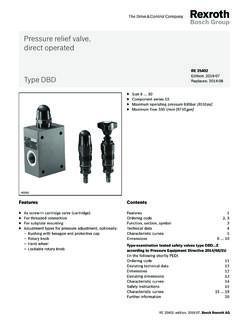
Transcription of Axial piston variable pump AA4VG Series 32
1 Axial piston variable pump AA4VG Series 32. RE-A 92003. Edition: Americas Replaces: High-pressure pump for applications in a closed circuit Size 28 to 125. Nominal pressure 5800 psi (400 bar). Maximum pressure 6500 psi (450 bar). Closed circuit Features Contents Integrated auxiliary pump for boost and pilot oil supply Type code 2. Flow direction changes smoothly when the swashplate Hydraulic fluids 5. is moved through the neutral position Shaft seal 6. Working pressure range 7. High-pressure relief valves with integrated boost Technical data 8. function NV Version without control module 11. With adjustable pressure cut-off as standard DG Hydraulic control, direct operated 11. Boost-pressure relief valve HD Proportional control, hydr., pilot-pressure related 12. Through drive for mounting of further pumps up to same HW Proportional control, hydraulic, mechanical servo 14. EP Proportional control, electric 16. nominal size EZ Two-point control, electric 18.
2 Large variety of controls DA Automatic control, speed related 19. Swashplate design ET Electric control, direct operated 22. Dimensions, size 28 to 125 23. Dimensions, through drive 48. Overview of mounting options 51. Combination pumps AA4VG + AA4VG 52. High-pressure relief valves 53. Pressure cut-off 54. Mechanical stroke limiter 54. Stroking chamber pressure port X3 and X4 55. Filtration in the boost pump suction line 56. Filtration in the boost pump pressure line 56. External boost pressure supply 59. Dimensions with filter fitted 60. Swivel angle sensor 61. Connector for solenoids 62. Rotary inch valve 63. Installation dimensions for coupling assembly 64. Installation instructions 65. Project planning notes 68. Safety instructions 68. Americas | RE-A 92003 , Bosch Rexroth AG. 2 AA4VG Series 32 | Axial piston variable pump Type code Type code 01 02 03 04 05 06 07 08 09 10 11 12 13 14 15 16 17 18 19 20 21 22.
3 AA4V G D / 32 N. Axial piston unit 01 Swashplate design , variable , nominal pressure 5800 psi (400 bar), maximum pressure 6500 psi (450 bar) AA4V. Operating mode 02 Pump, closed circuit G. Size (NG). 03 Geometric displacement, see Technical data on page 8 in3/rev. cm3/rev. 28 40 56 71 90 125. Control device 28 40 56 71 90 125. 04 Without control module NV. Proportional control, hydraulic Pilot-pressure related p = 87 to 260 psi (6 to 18 bar) HD3. Mechanical servo HW. Proportional control, electric U = 12 V EP3. U = 24 V EP4. Two-point control, electric U = 12 V EZ1. U = 24 V EZ2. Automatic control, speed related U = 12 V DA1. U = 24 V DA2. Hydraulic control, direct operated DG. Electric control, direct operated, U = 12 V ET5. two pressure reducing valves U = 24 V ET6. Pressure cut-off 05 Pressure cut-off (standard) D. Neutral position switch 06 Without neutral position switch (without code) . Neutral position switch (for HW control only) L.
4 Mechanical stroke limiter 07 Without mechanical stroke limiter (without code) . Mechanical stroke limiter, externally adjustable M. Stroking chamber pressure port 28 40 56 71 90 125. 08 Without stroking chamber pressure port X3, X4 (without code) . Stroking chamber pressure port X3, X4 T. DA control valve NV HD HW DG DA EP EZ. 09 Without DA control valve 1. DA control valve, fixed setting 2. DA control valve, mechanically adjustable with position direction of actuation, clockwise 3R. lever direction of actuation, 3L. counter-clockwise DA control valve, fixed setting, ports for pilot control device 7. DA control valve, fixed setting and based on mineral oil 8. brake inch valve mounted, control with brake fluid = Available = On request = Not available = Preferred program Bosch Rexroth AG, RE-A 92003 | Americas Axial piston variable pump | AA4VG Series 32 3. Type code 01 02 03 04 05 06 07 08 09 10 11 12 13 14 15 16 17 18 19 20 21 22.
5 AA4V G D / 32 N. Series 10 Series 3, index 2 32. Direction of rotation 11 Viewed on drive shaft clockwise R. counter-clockwise L. Sealing material 12 NBR (nitrile rubber), shaft seal in FKM (fluoroelastomer) N. Drive shaft 28 40 56 71 90 125. 13 Splined shaft for single pump S. ANSI for combination pump 1st pump 1). 1). 1). T. only for combination pump 2nd pump U. Mounting flange 28 40 56 71 90 125. 14 SAE J744 2-hole C. 2+4-hole F. Working port 28 40 56 71 90 125. 15 SAE working port A and B, top and bottom Suction port S bottom 52. SAE working port A and B, top and bottom Suction port S top 53. SAE working port A and B, same side right2) Suction port S bottom . 60. SAE working port A and B, same side left2) Suction port S bottom . SAE working port A and B, same side right2) Suction port S top 63. Boost pump 16 Without integrated boost pump without through drive N. with through drive K. Integrated boost pump with and without through drive F.
6 Through drive 3). 28 40 56 71 90 125. 17 Without through drive, versions N and F (no. 16) only 00. Flange SAE J744 4). Hub for splined shaft 82-2 (A) 5/8 in 9T 16/32DP5) 01. 101-2 (B) 7/8 in 13T 16/32DP 5). 02. 1 in 15T 16/32DP5) 04. 127-2 (C)6) 1 1/4 in 14T 12/24DP5) 07. 152-2/4 (D) 1 3/4 in 13T 8/16DP5) 69. = Available = On request = Not available = Preferred program 1) Standard for combination pump 1st pump: Shaft S 4) 2 = 2-hole; 4 = 4-hole 2) Only possible without attachment filter 5) Hub for splined shaft to ANSI 3) Specifications for version with integrated boost pump, please con- 6) NG90 to 125 with additional 4-hole-flange (127-4). tact us for version without boost pump Americas | RE-A 92003 , Bosch Rexroth AG. 4 AA4VG Series 32 | Axial piston variable pump Type code 01 02 03 04 05 06 07 08 09 10 11 12 13 14 15 16 17 18 19 20 21 22. AA4V G D / 32 N. High-pressure relief valve Setting range p 28 40 56 71 90 125.
7 18 High pressure relief valve, pilot operated 1450 to 6100 psi with bypass 1. (100 to 420 bar). High-pressure relief valve, direct operated, 3600 to 6100 psi without bypass 3. fixed setting (250 to 420 bar) with bypass 5. 1450 to 3600 bar without bypass 4. (100 to 250 bar) with bypass 6. Filtration boost circuit/external boost pressure supply 28 40 56 71 90 125. 19 Filtration in the boost pump suction line S. Filtration in the boost pump pressure line D. Ports for external boost circuit filtration (Fe and Fa). Mounted cold start valve and ports for external boost circuit filtration K. Attachment filter with cold start valve F. Attachment filter with cold start valve and visual contamination indicator P. Attachment filter with cold start valve and electric contamination indicator B. External boost pressure supply (version without integrated boost pump - N00, ) E. Swivel angle sensor 28 40 56 71 90 125. 20 Without swivel angle sensor (without code).
8 Electric swivel angle sensor7) R. Connector for solenoids8). 21 Without connector (without code), only for purely hydraulic control . DEUTSCH molded connector, 2-pin without suppressor diode P. with suppressor diode (only for EZ and DA) Q. Standard / special version 22 Standard version without code combined with attachment part or attachment pump -K. Special version -S. combined with attachment part or attachment pump -SK. = Available = On request = Not available = Preferred program Notice Note the project planning notes on page 68. In addition to the type code, please specify the relevant technical data when placing your order. 7) Please contact us if the swivel angle sensor is used for control 8) Connectors for other electric components may deviate Bosch Rexroth AG, RE-A 92003 | Americas Axial piston variable pump | AA4VG Series 32 5. Hydraulic fluids Hydraulic fluids The AA4VG variable pump is designed for operation with Notes on selection of hydraulic fluid HLP mineral oil according to DIN 51524.
9 The hydraulic fluid should be selected such that the Application instructions and requirements for hydraulic operating viscosity in the operating temperature range fluids should be taken from the following data sheets is within the optimum range ( opt see selection diagram). before the start of project planning: 90220: Hydraulic fluids based on mineral oils and Notice related hydrocarbons At no point of the component may the temperature be 90221: Environmentally acceptable hydraulic fluids higher than 240 F (115 C). The temperature difference 90222: Fire-resistant, water-free hydraulic fluids specified in the table is to be taken into account when (HFDR/HFDU) determining the viscosity in the bearing. 90225: Axial piston units for operation with water-free Please contact us if the above conditions cannot be met and water-containing fire-resistant hydraulic fluids due to extreme operating parameters. (HFDR, HFDU, HFAE, HFAS, HFB, HFC).
10 Viscosity and temperature of hydraulic fluids Viscosity [SUS (mm2/s)] Temperature Comment Cold start max 7400 (1600) St 40 F ( 40 C) t 3 min, n 1000 rpm, without load p 725 psi (50 bar). Permissible temperature difference T 45 F (25 K) between Axial piston unit and hydraulic fluid in the system Warm-up phase = 7400 to 1850 = 40 F to 13 F at p x pnom, n x nnom and t 15 min (1600 to 400) ( 40 C to 25 C). Continuous operation = 1850 to 60 this corresponds, for VG 46 for example, to a temperature range (400 to 10) of +41 F (5 C) to + 185 F (85 C) (see selection diagram). = 13 F to +230 F measured at port T. ( 25 C to +110 C) Observe the permissible temperature range of the shaft seal ( T = approx. 9 F (5 K) between bearing/shaft seal and port T). opt = 170 to 82 (36 to 16) Range of optimum operating viscosity and efficiency Short-term operation min 49 (7) t < 3 min, p < pnom Selection diagram SUS mm2/s Warm-up phase Maximum permissible viscosity for cold start 7000 (1600).