Transcription of B9512/B8512 UL Installation Guide - Bosch Security …
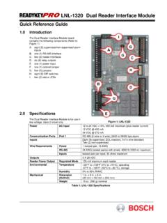
1 Control PanelsB9512G/B8512G (B9512G-E/B8512G-E) enUL Installation Guide IntroductionThis section includes an introduction to documents for this product and other document-related documentationThis document contains instructions for a trained installer to properly install, configure, andoperate this control panel, and optional peripheral devices. Review this document beforebeginning the Installation to determine the hardware and wiring requirements for the featuresused.( Bosch Security Systems, Inc. recommends that installers follow good wiring practices such asthose descibed in NFPA 731, Standard for the Installation of Electronics Premises SecuritySystems.)
2 Throughout this document, the words control panel refer to all control panels covered bythis document (B9512G/B8512G/B9512G-E/B8512G-E).Notifi cationsThis document uses Notices, Cautions, and Warnings to draw your attention to !These include important notes for successful operation and programming of equipment, orindicate a risk of damage to the equipment or environment.!Caution!These indicate a hazardous situation which, if not avoided, could result in minor or moderateinjury.!Warning!These indicate a hazardous situation which, if not avoided, could result in death or document is the intellectual property of Bosch Security Systems, Inc.
3 And is protected bycopyright. All rights hardware and software product names used in this document are likely to be registeredtrademarks and must be treated documentationControl panel documentsControl Panels (B9512G/B8512G) Release Notes *Control Panels (B9512G/B8512G) Installation and System Reference Guide (P/N: F01U303996)+Control Panels (B9512G/B8512G/B5512/B4512/B3512) Owner s Manual (English) (P/N:F01U307371)* +Control Panels (B9512G/B8512G) Program Entry Guide (P/N: F01U303998)+Control Panels (B9512G/B8512G) UL Installation Guide + (this document) (P/N: F01U304001)*+ PanelsIntroduction | en3 Bosch Security Systems, Installation | 05 | Panels (B9512G/B8512G) SIA Quick Reference Guide (P/N: F01U304000)* +Control Panels (B9512G/B8512G/B6512/B5512/B4512/B3512) ULC Installation Guide (P/N:F01U321698)*Shipped with the control panel.
4 +Located on the documentation CD shipped with the control documentsBasic Keypad (B915) Installation Guide (P/N: F01U297873)*Two-line Alphanumeric Keypad (B920) Installation Guide (P/N: F01U265450)*Fire Keypads (B925F/B926F) Installation Guide (P/N: F01U305193)*Two-line Capacitive Keypad with Inputs (B921C) Installation Guide (P/N: F01U297887)*ATM Style Alphanumeric Keypad (B930) Installation Guide (P/N: F01U265451)*Touch Screen Keypad (B942/B942W) Installation Guide (P/N: F01U294527)**Shipped with the module documentsOcto-input Module (B208) Installation and Operation Guide (P/N: F01U265456)*POPEX Module (B299) Installation Guide (P/N: F01U300043)*Octo-output Module (B308) Installation and Operation Guide (P/N: F01U265458)*Conettix Ethernet Communication Module (B426) Installation and Operation Guide (P/N:F01U281208)* +Plug-in Telephone Communicator (B430) Installation Guide Installation Guide (P/N:F01U265454)*Conettix Plug-in Cellular Communicator (B440) Installation and Operation Guide (P/N.)
5 F01U265455)*Conettix Plug-in CDMA Cellular Communicator (B441) Installation and Operation Guide (P/N:F01U282233)*Conettix Plug-in GPRS Cellular Communicator (B442) Installation and Operation Guide (P/N:F01U283180)*Conettix Plug-in HSPA+ Cellular Communicator (B443) Installation and Operation Guide (P/N:F01U283181)*Conettix Plug-in Communicator Interface (B450) Installation and Operation Guide (P/N:F01U300740)* +Auxiliary Power Supply (B520) Installation and Operation Guide (P/N: F01U265445)*Retrofit ZONEX Module (B600) Installation Guide (P/N: F01U300237)RADION receiver SD (B810) Installation Guide (P/N: F01U261834)*SDI2 Inovonics Interface Module (B820) Installation Guide (P/N: F01U265460)*Access Control Module (B901) Installation Guide (P:/N: F01U300416)Dual Class B Initiating Module (D125B) Installation instructions (P/N: F01U036340)4en | IntroductionControl | 05 | Installation GuideBosch Security Systems, Bus Interface (D8125 MUX) Operation and Installation Guide (P/N: F01U034973)OctoPOPIT Module (D8128D) Installation Guide (P/N.
6 F01U070537)Access Control Interface Module (D9210C) Installation and Operation Guide (P/N:F01U215232)*Shipped with the module.+Located on the documentation CD shipped with the module. Bosch Security Systems, Inc. product manufacturing datesUse the serial number located on the product label and refer to the Bosch Security Systems,Inc. website at following image shows an example of a product label and highlights where to find themanufacturing date within the serial PanelsIntroduction | en5 Bosch Security Systems, Installation | 05 | overviewB430 Plug-in Tephone Communicator provides a single telephone RJ-45 connector to allow communication over telephone lines.
7 ControlPanelOn-board Points1 to 8B44x Conettix Plug-In Cellular Communicator allows communciation over a cellular modules allow the addition of up to 8 input devices. B308 Octo-output modules allow the addition of up to 8 output devices. B520 Auxiliary Power Supply modules expand power by connecting to an SDI2 device bus or other 12 volt RADION receiver SDs connect RADION wireless devices to the control Inovonics Interface modules interface with an Inovonics wireless keypads* to operate the control panel by area. b9512 control panels support up to 32 areas.
8 b8512 control panels support up to 8 areas. Each area can have its own account number or you can group together areas with a common account number. B450 Conettix Plug-In Communicator Interface allows communciation over a cellular network through the SDI2 The B426 provides off-board communication over a modules provide support for up to 100 POPIT devices over a single expansion ZONEX modules allows the connection of ZONEX expansion modules. *Up to 8 of the keypads can be models D1260, D1257/D1257RB, D1256/D1256RB, orD1255/D1255R/D1255RB on the SDI bus (SDIx configured as SDI).
9 2 6en | System overviewControl | 05 | Installation GuideBosch Security Systems, panel installationThis section explains how to mount the control panel enclosure, how to mount the controlpanel into the enclosure, and provides an overview of how to wire modules to the overviewBefore you begin, review the overview figure:Figure : Enclosure and control panel mounting overviewCallout DescriptionCallout Description1 Mounting skirt attachment hooks (2)5 Enclosure mounting holes (5)2 Module mounting three-hole pattern (4)6 Mounting skirt attachment holes (2)3 Tamper switch mounting location7 Back of the control panel mounting skirt4 Mounting skirt screw location (1)8 Mounting skirt screw tabInstall the enclosureRefer to Enclosures to determine if the application requires a specific the enclosure:1.
10 Remove any knockouts prior to installing the control Mount the enclosure in the desired location. Use all enclosure mounting holes. Refer tothe mounting instructions supplied with the selected Pull the wires into the Optionally install the supplied point label chart on the inside of the enclosure !Electromagnetic interference (EMI) can cause problems on long wire PanelsControl panel Installation | en7 Bosch Security Systems, Installation | 05 | the control panelThis section includes instructions to mount the control panel in the enclosure, connect earthground, and make other control panel the control panelRefer to the figure Enclosure overview, page the control panel:1.