Transcription of LNL-500 Intelligent System Controller
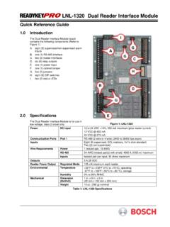
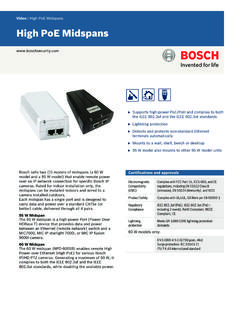
1 LNL-500 Intelligent System Controller Quick Reference guide For detailed information, please refer to the LNL-500 tab in the READYKEYPRO Hardware installation guide (49289). The ISC Board The ISC board contains the following components (Refer to Figure 1): A. two (2) unsupervised alarm inputs B. one (1) RS-232 or RS-485 interface C. two (2) downstream RS-485 interfaces (which can consist of one 4-wire and two 2-wire interfaces) D. a set of three (3) status LEDs E. one (1) bank of eight (8) dip switches F. eleven (11) jumpers G. one (1) power-in input H. and one (1) memory backup (3 volt lithium) battery I. one (1) TCP/IP Connector Figure 1: LNL-500 Unsupervised Alarm Input Wiring GNDCABINETTAMPERPOWERFAULTGNDIN2IN1 Figure 2: Unsupervised Alarm Input Wiring If either of these inputs is not used, a jumper wire should be installed.
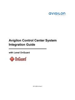
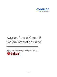
2 If RS-485 communication is used, an RS-232 to RS-485 converter is required at the host workstation. LNL-500 LNL-500 Quick Reference guide 49305D Page 2 2006 Bosch Security Systems, Inc. Wiring Configuration Port 1 ISC 9-pin 25-pin TXD/TR1+ pin 2 pin 3 RXD/TR1- pin 3 pin 2 RTS/R1+ not used not used CTR/R1- pin 7 pin 4 GND pin 5 pin 7 Jumper together 4, 6 & 8 5, 6 & 20 This configuration will work for Direct Connect (RS-232) and Lantronix Ethernet network communications. With direct connect, or Dial-up DIP switch 5 needs to be OFF, and with Lantronix, DIP switch 5 needs to be ON. Table 1: LNL-500 Pinout Connections PORT 1, CONFIGURED ASRS-232TR1+TR1-GNDR1 -R1 +4-WIRETR- TR+ R- R+ SGPORT 1, CONFIGURED AS RS-485 TXD/TR1+RXD/TR1-GNDCTS/R1 -RTS/R1 +TXD/TR1+RXD/TR1-GNDCTS/R1 -RTS/R1 +2-WIRETO RS232/RS485 CONVERTERTO RS232/RS485 CONVERTERTo P CRS-4852-WireConfigurationRS-4854-WireCo nfigurationRS-232 DirectConnection Figure 3: Upstream Host Communication Wiring (Port 1) If Using A 12 VDC Power Source, Be Sure To Observe Polarity.
3 VINGND12 to 24 VDC+- Figure 4: Power Source Wiring Port 2 and Port 3 To configure all four downstream ISC ports as 2-wire RS-485, follow the 2-wire diagram and repeat on each set of three terminators, TR2+, TR2-, GND and TR3+, TR3-, GND Port 2/3 TR2+, TR2- TR3+, TR3- GND To configure as a 4-wire RS-485 ports, follow the 4-wire diagram (Table 2). Must terminate the RS-485 at each end-of-line device. Table 2: Ports 2-3, RS-485 LNL-500 LNL-500 Quick Reference guide 2006 Bosch Security Systems, Inc. Page 3 49305D DIP Switches DIP Switch(es) USED TO CONFIGURE: 1, 2, 3, 4 Processor address (0 7) 5 Communication handshake status ( CTS enabled or none ) 6, 7 Communication baud rate (38400, 19200, 9600 bps) 8 Not Used The ISC board contains 8 DIP switches that must be configured appropriately for your System .
4 Figure 5 shows the default address of 0, CTS enabled, and baud rate set to 38,400 bps. 1ON234567 8 Figure 5: DIP Switch Settings Table 3: DIP Switch Settings Processor Address DIP Switch Address 1 2 3 4 Default 0 OFF OFF OFF OFF 1 ON OFF OFF OFF 2 OFF ON OFF OFF 3 ON ON OFF OFF 4 OFF OFF ON OFF
5 5 ON OFF ON OFF 6 OFF ON ON OFF 7 ON ON ON OFF Table 4: Processor Address Communication Handshake Status HANDSHAKE STATUS: DIP SWITCH 5 Transmit enabled by CTS ON Default None off Table 5: Handshake Status Communication Baud Rate (upstream and downstream) DIP SWITCH BAUD RATE: 6 7 38,400 bps ON ON Default 19,200 bps off ON 9600 bps ON off off off Table 6: Communication Baud Rate Note.
6 The READYKEYPRO Intelligent System Controller does not currently support this feature. Therefore, set DIP switch 8 to the off ( Not used ) position, according to the following table. PASSWORD STATUS: DIP SWITCH 8 NOT USED off Default Table 7: Password Status 2006 Bosch Security Systems, Inc. 130 Perinton Parkway, Fairport, NY 14450-9199 USA Customer Service: (800) 289-0096; Technical Support: (888) 886-6189 49305D Quick Reference guide 10/06 LNL-500 Page 4 of 4 Installing Jumpers Jumper(s) Used to configure: J3,J4,J5,J6,J9 Port 1 communication interface type (RS-485, RS-232) J7 Port 1 RS-485 type (2-wire, 4-wire) J8, J10 Port 1 EOL termination status (On, Not On) J11 Port 2 EOL termination status (On, Not On) J12 Port 3 EOL termination status (On, Not On) J13 Port 1 Serial (RS-232), Ethernet The ISC board contains 11 jumpers that must be configured appropriately for your System .
7 Table 8 describes the use of each jumper on the ISC board. Table 8: Jumper Configuration J72W4W 2-Wire Configuration for Jumper J7 J72W4W 4-Wire Configuration for Jumper J7 Figure 6: Port 1 RS-485 Type J3J5J6J9J4 RS-232 Configuration for Jumpers J3, J4, J5, J6, J7, J9 J3J5J6J9J4 RS-485 Configuration for Jumpers J3, J4, J5, J6, J7, J9 J8J11 EOL Terminator On Configuration for Jumpers J8, J10 J8J11 EOL Terminator Not On Configuration for Jumpers J8, J10 Figure 7: Communication Interface Type Figure 8: Port 1 RS-485 EOL Terminator Status J11 EOL Terminator On Configuration for Jumper J11 J11 EOL Terminator Not On Configuration for Jumper J11 J12 EOL Terminator On Configuration for Jumper J12 J12 EOL Terminator Not On Configuration for Jumper J12 Figure 9: Port 2 RS-485 EOL Terminator Status Figure 10: Port 3 RS-485 EOL Terminator Status J13 Serial or Dial-up Configuration for Jumper J13 J13 Ethernet Configuration for Jumper J13 Figure 11: Port 1 RS232, Serial, Ethernet Type