Transcription of Back-UPS CS 350/500/650 - CNET Content
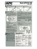
1 USBRJ-45In situations where the Back-UPS or connected equipment appears too sensitive to input voltage, it may benecessary to adjust the transfer voltage. This is a simple task requiring use of the front panel pushbutton. Toadjust the transfer voltage, proceed as follows:1. Plug the Back-UPS into the utility power source. The Back-UPS will be in a Standby Mode (no indicators lit).2. Press the front panel pushbutton fully inward for 10 seconds. All indicators on the Back-UPS will flash toacknowledge going into Programming The Back-UPS will then indicate its current Sensitivity Setting, as shown in the following To select the Low Sensitivity setting, press the pushbutton until the yellow indicator is To select the Medium Sensitivity setting, press the pushbutton until the yellow and red indicators (second andthird from the top) are To select the High Sensitivity setting, press the pushbutton until yellow and both red indicators (bottom three)are To exit without changing the Sensitivity Setting, press the pushbutton until the green indicator is Once in Programming Mode, if the pushbutton is not pressed within 5 seconds, the Back-UPS will exitProgramming Mode; all indicators will VoltageRange(for utility operation)Use When1(yellow)Low160 - 278 VacInput voltage is extremely low or high.
2 Not recommended for computer (yellow, and red)Medium(factory default)180 - 266 VacBack-UPS frequently goes On (yellow, red, and red)High196 - 256 VacConnected equipment is sensitive to voltage fluctuations (recommended). Back-UPS 350/500/650 User s Manual990-9237 3/04 Installation2 Connect EquipmentThe rear panel of the Back-UPS consists of thefollowing elements:Battery back Up Outlets (qty. of 3). Theseoutlets provide battery back -up, surge protection,and Electro-magnetic Interference (EMI) case of power outage, battery power isautomatically provided to these outlets. Power(utility or battery) is not supplied to these outletswhen the Back-UPS is switched Off. Connect acomputer, monitor, and external disk or CD-ROMdrive to these Only Outlet. This outlet is always On(when utility power is available) and is notcontrolled by the On/Off switch.
3 This outlet doesnot provide power during a power outage. Connecta printer, fax machine or scanner to this : Allow the Back-UPS to charge for a full eighthours prior to the push-button on the front panel of the that the following events occur afterpressing and releasing the push-button: The green On-Line indicator flashes. The yellow On Battery indicator lights whilethe Self-Test is being performed. When Self-Test has successfully completed,only the green On Line indicator will be lit. If the internal battery is not connected, (see Step1 above) the green On Line indicator and redReplace Battery indicator will light. The Back-UPS will also emit a chirping LINEON BATTERYOVERLOADREPLACE BATTERY5 Connect USB CableThere are four status indicators (lights) on the frontpanel of the Back-UPS (On Line, On Battery,Overload, and Replace Battery).
4 On Line (green) - is lit whenever utilitypower is powering the Battery LINEON BATTERYOVERLOADREPLACE BATTERYOn Battery (yellow) - is lit wheneverthe battery of the Back-UPS is poweringequipment connected to the BatteryBackup Beeps Every 30 Seconds - thisalarm is sounded whenever the Back-UPS is running On Battery. Considersaving work in Beeping - this alarm issounded whenever a low batterycondition is reached. Battery run-timeis very low. Promptly save any workin progress and exit all openapplications. Shutdown the operatingsystem, computer and the (red) - is lit wheneverpower demand has exceeded the capac-ity of the Tone - this alarm issounded whenever the Battery Backupoutlets are Breaker - the circuitbreaker button located on the rearpanel of the Back-UPS will stickout if an overload condition forcesthe Back-UPS to disconnect itselffrom utility power.
5 If the buttonsticks out, disconnect non-essential equipment. Reset thecircuit breaker by pushing thebutton / Power3 Connect the PhoneLine to Surge ProtectionAvoid placing the Back-UPS in: Direct sunlight Excessive heat Excessive humidity or in contact with fluidsof any typePlug the Back-UPS into a wall outlet, as shown. The Back-UPS charges the internal batteryany time it is connected to a wall computer s power telephone ports provide lightning surgeprotection for any device connected to the telephoneline ( computer , modem, fax or telephone). Thetelephone ports are compatible with Home PhonelineNetworking Alliance (HPNA) and Digital SubscriberLine (DSL) standards, as well as all modem datarates. Connect as OutletModem/Phone/FaxReplace Battery (red) - is lit when-ever the battery is near the end of its use-ful life, or if the battery is not connected(see above).
6 A battery that is near theend of its useful life has insufficient run-time and should be for 1 Minute Every 5 Hours -this alarm is sounded whenever thebattery has failed the automaticdiagnostic to the back -UPS4 Switch on theBack-UPSR eplace the Internal BatteryTo replace the internal battery, proceed as follows: Note: Replacing the battery is a safe procedure. However, small sparks may occurduring the process. This is the unit on its side. Slide the battery compartment cover upward and off of the Align the battery compartment cover with the grooves in the UPS. Slide the cover down until it the battery out, exposing the battery terminals and wires. Disconnect the wires from the the new battery into the battery compartment. Connect the battery wires to the terminals as follows:Black wire to Ground (-) terminalRed wire to Positive (+) terminaland Install Software(optional)NOTE: Macintosh Users - for full USBperformance, use Mac OS or Autoplay is not enabled on the computer ,proceed as follows:1.
7 On the computer desktop of the display,double-click on My Double-click on the CD-ROM drive icon andfollow the on-screen Indicators and AlarmsOrder Replacement BatteryThe typical battery lifetime is 3-6 years (depending on the number of discharge cycles and operatingtemperature). A replacement battery can be ordered over the phone from APC, or the battery can be orderedon-line from the APC web site ( , a valid credit card is required).When ordering, please specify Battery Cartridge RBC2 ( Back-UPS 350/500) or RBC17 ( Back-UPS 650).Transfer Voltage and Sensitivity Adjustment (optional)APC, Back-UPS , and PowerChute are registered trademarks of American Power other trademarks are property of their respective does not power computer /monitor/external drive during an outageInternal battery is not , monitor or external disk/CD-ROM drive is plugged into aSurge Only the battery connectionsMove computer , monitor, or external drive power cord plug to theBattery Backup operates on battery although normal utility voltage existsBack-UPS circuit breaker tripped.
8 The wall outlet that the Back-UPS isconnected to does not supply utilitypower to the non-essential equipment from theBack-UPS. Reset the circuit breaker (locatedon the rear panel of the Back-UPS ) by push-ing the circuit breaker button fully inwarduntil it does not provide expected backup timeBack-UPS is excessively battery is weak due torecent outage and has not had timeto requires non-essential Battery Backup connected equipment, such asprinters and plug them into Surge Only : Devices that have motors or dimmer switches (laser printers,heaters, fans, lamps, and vacuum cleaners, for example) should not beconnected to the Battery Backup the battery. The battery charges whenever the Back-UPS isconnected to a wall outlet. Typically, eight hours of charging time areneeded to fully charge the battery from total discharge. back -UPSrun-time is reduced until the battery is fully battery (see Order Replacement Battery).
9 Batteries typicallylast 3-6 years, shorter if subjected to frequent power outages or ele-vated red indicator is litBattery is not connected Overload indicator is lit ifequipment connected to the BatteryBackup outlets is drawing morepower than the Back-UPS can requires the battery one or more equipment power plugs to the Surge Only battery should be replaced within two weeks (see "OrderReplacement Battery"). Failure to replace the battery will result inreduced run-time during a power the Back-UPS to another wall outlet or have a qualifiedelectrician check the building indicators are flashingBack-UPS APC for service. the Troubleshooting section to eliminate common if the circuit breaker is tripped. If the circuit breaker is tripped, reset the breaker and determine if the problem still the problem persists, consult the APC Worldwide Web site ( ) or call customer service.
10 Record the model number of the UPS, the serial number, and the date purchased. Be prepared to troubleshoot the problem over the telephone with a technician. If this is not successful, the technician will issue a Return Merchandise Authorization Number (RMA#) and a shipping address. If the UPS is under warranty, repairs are free. If not, there is a repair the UPS in its original packaging. If the original packing is not available, ask customer service about obtaining a new set. Pack the UPS properly to avoid damage in the RMA# on the outside of the the UPS by insured, prepaid carrier to the address provided by customer : If the UPS requires service, do not return it to the dealer. The following steps should be taken:Note: Never use StyrofoamTM beads for packaging. Damage sustained in transit is not covered under warranty (insuring the package for full value is recommended).WarrantyThe standard warranty is two (2) years from the date of purchase.