Transcription of BALANCING BASICS - Comdronic
1 BALANCING BASICS 1 Introduction 2 Background 3 Flow of water through systems 4 Valve types 5 Valve identification 6 Taking readings 7 Taking readings with electronic manometers 8 System BALANCING Comdronic Ltd would like to extend gratitude to the following Companies for the photographic images that support this document. Crane Fluid Systems Oventrop UK Ltd 1. Introduction A basic discussion of the processes involved to establish the flow of water through valves which, in turn, will lead to the BALANCING of water flows in the various parts of a water based system.
2 BALANCING BASICS is intended to be used by engineers and technicians who are not specifically trained as commissioning engineers. I can also be used as a reference for those training to become commissioning engineers. 2. Background The flow of water in a system with multiple branches and terminals might at first glance seem mystifying, however, a basic knowledge of the physics involved will help to clarify the process. The type of system we are interested in for flow BALANCING is a closed loop system such as a heating system or chilled water system.
3 Those of us with central heating systems at home have all endeavoured to get the balance right in the system by simply adjusting each radiator until it feels about right This process is ok if we have enough time, however, if the system is large, such as a commercial heating system then the process has to be formalised to ensure correct building comfort. 3. Flow of water through systems. If we are to ensure that the space is heated or cooled by the correct amount we have to make sure that the flowrate of water to the space is in keeping with the requirements set out by the design engineer.
4 Each space will have been analysed for heat loss/gain and a heating/cooling load in KW (Kilowatts) determined. In order to transport the KW to the space we use water either heated or cooled. The designer will normally convert the KW value into flow rate using the formula: Mass flow rate= Emitter output (kw) / Specific heat capacity for water X t (Deg C) For heating the temp change ( t)in the emitter is usually 11 Degrees For cooling the temp change ( t)in the emitter is usually 6 Degrees The specific heat capacity of water is kj/kgC Because the t in cooling is less than that in heating we can see that for each kw delivered to the space we will need more water if it is cooling.
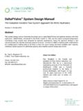
5 Do not let any of the above cause you concern because the designer will have already carried out the calculation for flow rates and it is this that we are interested in. The basic building block for the commissioning engineer is the BALANCING valve. This is a generic term for a variety of valves used for BALANCING systems. There are 4 main varieties of traditional device as described below. 4 Valve types Double regulating valves (DRV) For flow regulation only. Typically this valve is a Y pattern globe valve arranged in this way to present the smallest pressure loss to the system when fully open.
6 Adjustment of this valve will add resistance to the system and hence reduce the flow. The description DOUBLE regulating means that it has a feature whereby you can set the position that the valve is to operate at in such a way that you can still close the valve for maintenance purposes. When using computerised electronic manometers with a valve database you will not find any data relating to these valves because they do not have a measuring facility. Flow measurement devices and valves (FMD/FMV) For flow measurement with or without isolation facility.
7 These devices are usually fixed orifice devices. More recently there has been more venturi devices appearing on the market (Mostly from US). A fixed orifice is the simplest device that we can use for measurement. The fixed orifice can be used on its own or with an isolating valve fitted downstream to provide isolation. Installed on their own these devices can give the most accurate results. When using electronic manometry to display the flow through this product the Maker, model and size of the unit must be entered into the meter.
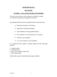
8 (See section Taking readings ) Photographs courtesy of Crane Fluid Systems Double regulating valves combined with flow measurement devices (FODRV) For regulation and flow measurement combined in one valve unit based on the Fixed Orifice principle. This combined assembly traditionally was assembled from a double regulating valve and fixed orifice device. More commonly nowadays the orifice is fitted directly into the body of the valve. When made up of a regulating valve and separate orifice the unit is often referred to as a Commissioning set When using electronic manometry to display the flow through this product the Maker, model and size of the unit must be entered into the meter.
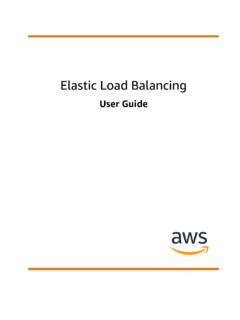
9 (See section Taking readings ) Double regulating valves with integral flow measurement facility. (VODRV) For regulation and flow measurement combined in one valve unit based on the variable orifice principle. Shown in the photo is a cast iron VODRV which allows the measurement of the flow across the entire valve. There is no fixed orifice fitted to this valve the signal measured on an electronic manometer relates to the loss across the whole valve When using electronic manometry to display the flow through this product the Maker, model and size of the unit must be entered into the meter.
10 (See section Taking readings ) Because the signal being measured on this valve relates to the loss across the entire valve the size of the signal depends on the position of the handwheel. This process will be dealt with in some detail later and really only affects those working on systems overseas. The use of this type of valve is popular in Europe and Ex Russian states. Photographs courtesy of Crane Fluid Systems 5 Valve identification Before any readings can be taken it is important to identify the type of valve or orifice device being used.