Transcription of Basic Interference Mechanisms Understanding and ...
1 1 Understanding and Eliminating RF InterferenceJim Brown K9 YCAudio Systems Group, Interference Mechanisms Audio cables are antennas Pin 1 problems Shield-current-induced noise (SCIN) Inadequate filtering of equipment ins and outs Audiofool DC-to-daylight design philosophy Shield current can excite all of theseSources of Shield Current Noise voltage on ground at ends of cable Filter capacitors on the power line Leakage capacitance in power transformers Current flowing in ground unrelated to audio system (motors, lighting equipment, etc.) Wiring errors Induced by magnetic fields Double-bonded neutrals Big transformers and motors radio transmitters (antenna action)The Pin 1 Problem Current flows on cable shields Hum, buzz, RF If shield goes to shielding enclosure, current stays outside the box If shield goes to the circuit board, current goes insidethe box!
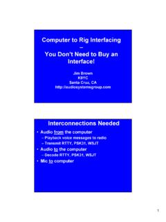
2 The Pin 1 ProblemThe Pin 1 Problem2It s in Unbalanced Circuits Too!It s in Unbalanced Circuits Too!Some Classic Pin 1 ProblemsA Classic Pin 1 ProblemAn Effective (but Ugly) Fix3RF in the Shack is a Pin 1 Problem Nearly all ham gear has pin 1 problems Mic inputs Keying inputs Control inputs and outputs Nearly all computers have pin 1 problems Sound cards Serial ports Great radio , Has Pin 1 ProblemsTen Tec Omni VA Pin 1 Problem? MaybeWhere are the Chassis Connections for this laptop s sound card? Hint: It isn t an audio connector shell! That metal is a shield, but not connected to connectors! And the cover is plastic too!
3 4 Where are the Chassis Connections for this laptop s sound card? Yes, it s the DB9 and DB25 shells! Too Much Bandwidth Wiring often puts RF on equipment inputs (and outputs) Equipment must be able to reject it! Audio spectrum ends at 20 kHz Filters produce phase shift Phase shift in multiple stages adds up Small rolloffs ( dB) add up So 100 kHz is a reasonable cutoff Going beyond 200 kHz is CRAZY!The AudioFool Viewpoint The Myth: We can hear stuff above 20 kHz Reality: Some distortion Mechanisms DO produce audible artifacts from ultrasonic signals, but we hear the problems, not the signals! Intermodulation distortion (40 kHz 30 kHz = 10 kHz) Slew rate limiting within electronics of ultrasonic output of a mic (or of square waves from a test generator)Golden Rules to Avoid RFI All wiring can act as an antenna It can receivecurrent if RF is present It can transmitRF if RF current flows on it radio signals cause current to flow Don t let that current cause problemsGolden Rules to Avoid RFI Fix pin 1 problems Fix equipment with excessive bandwidth Add low-pass filters at inputs Input transformers are inherently good low-pass filters (Jensen, Lundahl)
4 Faraday shield blocks common modeDifferential Mode Response of Jensen Isolation TransformerApproximates a 3-pole, 300 kHz low pass filter!5 Golden Rules to Avoid RFI Loudspeaker Cables Always use TWISTED PAIR Shielding is notimportant Exotic cable is a waste of money Mic and Line level Cables Avoiddrain wires in shields Use braid shielded cable Use twisted pair (tighter twist helps too)Golden Rules to Avoid RFI Maximize audio levels on cables Run outputstages near their maximumlevels Set inputgains near their minimumlevelsCritical Product Specifications Maximize inputlevel How much signal does it take to clip the inputstage?
5 Maximum outputlevel How much can the box put out cleanly?Output StageInput StageNoise = 500 V+250 mV avg1 V peaks)Signal to noise = 54 dB Gain at minimumOutput StageInput StageNoise = 500 V+50 mV avg200 mV peaks)Signal to noise = 40 dB Gain at maximumOutput StageXmtr Mic InputRF from AntennaMatching a Computer Output to a Transmitter V26 mVThe pad attenuates the computer output to match the mic input. It also attenuates any hum, buzz, or RF picked up on the input wiring. 6 Golden Rules to Avoid RFI RFI often enters equipment (and systems) by more than one path. Always assume that there are other paths!
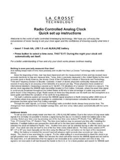
6 Take a methodical approach. Don t give up when one right technique doesn t fix it keep on doing other right things. The right techniques really are right! Golden Rules to Avoid RFI And when that isn t enough:Ferrites can block the current!An AM Broadcast Choke 14 turns of mic cable around this ferrite can kill AM broadcast RFIThis Clamp-On forms a choke that can kill Interference from FM and TVWhat s a Ferrite? A ceramic consisting of an iron oxide manganese-zinc MF, HF (AM broadcast, hams) nickel-zinc VHF, UHF (FM, TV, cell phones) Has permeability much greater than air Better path for magnetic flux than air Multiplies inductance of a wire passed through it Is increasingly lossy at higher frequencies Does not affect audio 7 Permeability Symbol is 0 is permeability of free space (air, aluminum) ron data sheets is usually the relativepermeability, referenced to free space Subscript r usually omitted Typical values Steel 1,000 Stainless steel 500 Mu-metal 20,000 Ferrites 100 3,000 A (too)
7 Simple equivalent circuit of a wire passing through a ferriteRsand Xsvary with frequency!A Ferrite Optimized for UHF3 turnsZ for multi-turn chokes on a toroid(Fair-Rite #78)ZN= N2*Z1A material useful on the AM broadcast Band#78 material useful on the AM broadcast BandRSfor multi-turn chokes on a toroidRN= N2* R185 turnsXSfor multi-turn chokes on a toroid XN= N2 .X1#78 material useful on the AM broadcast Band5 turnsParallel Resonance!What Causes this Resonance?The ferrite material (the mix), andThe physical dimensions of the ferrite core. There is a finite velocity of propagation within the ferrite There are standing waves within the core when the cross-section is a half-wavelength Frequency of the resonance depends on: Velocity of propagation (depends on the mix ) Dimensions of the cross-section of the flux pathRsand Xsvary with frequency!
8 Same material, different lengths!LongerShorterA Ferrite Mix Optimized for UHF9 Audio Cable is Lossy at RF RF is detected within equipment. RF that gets in at a distance will be attenuated by the cable. It s RF that gets onto the cable close to the equipment that matters most. So put the ferrite choke very close to the equipment that is detecting the RFLet s Test Our Equivalent CircuitIt looks OK for the #78 material at lowfrequencies, but look at high frequencies there is another resonance up there!LDand CD describe the dimensional accounts for the lossesin the ferrite. We need a more com-plex equivalent circuit.
9 LCis the inductance of the coilCCis the stray capacitance of the coilRCis the resistance of the CCis the resonance that moves!WireFerriteGeneral Equivalent CircuitImpedance of Multi-turn Chokes on #78 ToroidImpedance of Chokes on #43 ToroidThere s only one resonance here the coilImpedance of Multi-turn Chokes on #43 Toroid10 Why no Dimensional Resonance?The #78 is MnZn, while this one is NiZn VPin #43 is much higher, so dimensional resonance would occur at VHF rather than MF At VHF, there is so much loss that it damps the standing waves that would produce dimensional resonanceImpedance of Multi-turn Chokes on #61 ToroidData Sheets Show the ResonanceResonanceImpedance of Multi-turn Chokes on #77 ToroidImpedance of Multi-turn Chokes on #43 ToroidImpedance of Multi-turn Chokes on #31 Toroid11 Impedance of Multi-turn Chokes on #61 ToroidA Simple Bead (#43) works for VHFA Multi-turn Choke (#43)
10 Is needed for lower frequenciesDifferent Tools for Different ProblemsSo How do We Use These Tools?A Choke Applied to a Mic CableIt s a voltage divider!The Choke can Resonate with the AntennaA short antenna will look cancel some or all of XC antCurrent will increase, unlessRSlimits it so, for effective suppression: RSshould always be large!Equipment Not Well GroundedVoltage divider less effective!12 Criteria for Good Suppression Choke should be predominantly resistive With voltage divider (capacitor across input) A few hundred ohms can be very effective No voltage divider (brute force) At least 700 ohms needed, more is better 700 1,000 ohms RSshould be a minimum design goal Capacitance Can Help a Lot Outside the box, we re stuck with what the designer provided, so a big ferrite is needed Inside the box, we can use a smaller ferrite part if we provide the capacitorYou May Not Need an Elephant Gun Most detection is square law, so.