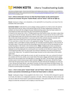
Transcription of BATTERY & WIRING INSTALLATION - Minn Kota Motors
1 Johnson Outdoors Marine Electronics, Power Drive, Mankato, MN 56001 Rev. & WIRING INSTALLATION BOAT RIGGING & PRODUCT INSTALLATIONFor safety and compliance reasons, we recommend that you follow American Boat and Yacht Council (ABYC) standards when riggingyour boat. Altering boat WIRING should be completed by a qualified marine technician. The following specifications are for generalguidelines only: CAUTION:These guidelines apply to general rigging to support your minn Kota motor . Powering multiple Motors or additional electrical devicesfrom the same power circuit may impact the recommended conductor gauge and circuit breaker size. If you are using wire longer thanthat provided with your unit, follow the conductor gauge and circuit breaker sizing table below. If your wire extension length is morethan 25 feet, we recommend that you contact a qualified marine MORE INFORMATION ON BATTERIES AND BATTERY CHARGERS VISIT CAUTION:An over-current protection device (circuit breaker or fuse) must be used.
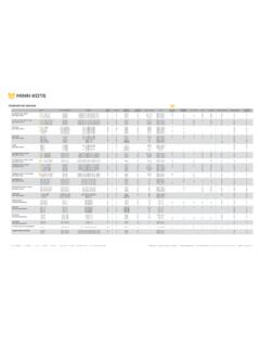
2 Coast Guard requirements dictate that each ungroundedcurrent-carrying conductor must be protected by a manually reset, trip-free circuit breaker or fuse. The type (voltage and current rating)of the fuse or circuit breaker must be sized accordingly to the trolling motor used. The table below gives recommended guidelines forcircuit breaker sizing. CONDUCTOR GAUGE AND CIRCUIT BREAKER SIZING TABLEThis conductor and circuit breaker sizing table is only valid for the following assumptions:1. No more than 2 conductors are bundled together inside of a sheath or conduit outside of engine Each conductor has 105 C temp rated No more than 5% voltage drop allowed at full motor power based on published product power requirements. motor THRUST / MODELMAXAMP DRAWCIRCUIT BREAKERWIRE EXTENSION LENGTH5 feet10 feet15 feet20 feet25 feet30 lb3050 Amp @ 12 VDC10 AWG10 AWG8 AWG6 AWG4 AWG40 lb.
3 , 45 Amp @ 12 VDC10 AWG8 AWG6 AWG4 AWG4 AWG50 lb., 55 lb5060 Amp @ 12 VDC8 AWG6 AWG4 AWG4 AWG2 AWG70 Amp @ 24 VDC10 AWG10 AWG8 AWG8 AWG6 AWG80 lb5660 Amp @ 24 VDC 8 AWG8 AWG8 AWG6 AWG6 AWG101 Amp @ 36 VDC 8 AWG8 AWG8 AWG8 AWG8 AWGE ngine Mount 10150 60 Amp @ 36 VDC 8 AWG8 AWG8 AWG8 AWG8 AWG112 Amp @ 36 VDC 8 AWG8 AWG8 AWG8 AWG8 AWGE ngine Mount 160116(2) x 60 Amp @ 24 VDC 6 AWG6 AWG4 AWG2 AWG2 AWGE-Drive4050 Amp @ 48 VDC10 AWG10 AWG10 AWG10 AWG10 AWGNOTICE: Wire Extension Length refers to the distance from the batteries to the trolling motor leads. Consult website for available thrust options. Maximum Amp Draw values only occur intermittently during select conditions and should not be used as continuous amp load States Code of Federal Regulations: 33 CFR 183 Boats and Associated Equipment ABYC E-11: AC and DC Electrical Systems on BoatsJohnson Outdoors Marine Electronics, Power Drive, Mankato, MN 56001 Rev.
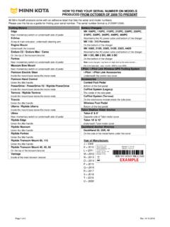
4 & WIRING INSTALLATIONFOR MORE INFORMATION ON BATTERIES AND BATTERY CHARGERS VISIT CONDUCTOR GAUGE AND CIRCUIT BREAKER SIZING TABLE - SHALLOW WATER ANCHORSMODELMAXAMP DRAWCIRCUIT BREAKERWIRE EXTENSION LENGTH5 feet10 feet15 feet20 feet25 feetTALON3050 Amp @ 12 VDC10 AWG10 AWG8 AWG6 AWG4 AWGRAPTOR7050 Amp @ 12 VDC10 AWG8 AWG6 AWG4 AWG4 AWGJ ohnson Outdoors Marine Electronics, Power Drive, Mankato, MN 56001 Rev. THE CORRECT BATTERY Advice Regarding Batteries: 1. Never connect the (+) and the (-) terminals of the same BATTERY together. Take care that no metal object can fall onto the BATTERY and short the terminals. This would immediately lead to a short and extreme fire It is highly recommended that a circuit breaker or fuse be used when installing a trolling motor . Refer to the minn Kota Conductor Gauge and Circuit Breaker Sizing Table.
5 For Motors requiring a 60-am breaker, the minn Kota MKR-19 60-amp circuit breaker is recommended. 3. Batteries should be stored and maintained at full charge. Failure to recharge lead-acid batteries (within 12-24 hours) is the leading cause of premature BATTERY failure. minn Kota offers a wide selection of chargers to fit your needs and application. 4. If using a crank BATTERY to start a gasoline outboard, we recommend that you use separate deep cycle marine BATTERY /batteries for your minn Kota trolling motor . What type of BATTERY do I need to run my minn Kota Trolling motor : A minn Kota trolling motor will operate with any lead acid, deep cycle marine 12-volt BATTERY /batteries. For best results, use a deep cycle, marine BATTERY with at least a 110-ampere hour rating. RUN-TIME VOLTAGE GROUP SIZEBMP-HOUR Good12 24 70-85 Better12 2785-110 Best12 3195-125 FOR MORE INFORMATION ON BATTERIES AND BATTERY CHARGERS VISIT Caution1.
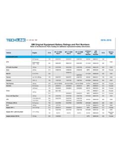
6 For safety reasons do not switch the motor on until the propeller is in the water. If installing a lead wire plug, observe proper polarity and follow instructions in your boat owner s manual. 2. For safety reasons, disconnect the motor from the BATTERY or batteries when the motor is not in use or while the BATTERY /batteries are being charged. 3. Improper WIRING of 24/36/48-volt systems could cause BATTERY explosion! 4. Keep wire wing nut connections tight and solid to BATTERY terminals. 5. Install BATTERY in a ventilated compartment. Johnson Outdoors Marine Electronics, Power Drive, Mankato, MN 56001 Rev. TO CONNECT BATTERIES IN A SERIES 24 Volt Systems (2 Batteries)1. Two 12-volt deep cycle batteries are Make sure that the trolling motor is switched to the off position or speed selector set to 0 .3. Wire in series only as directed in WIRING diagram, to provide 24 Connect a connector cable to the positive (+) terminal of BATTERY 1 and to the negative (-) terminal of BATTERY Connect positive (+) red lead (from motor ) to positive (+) terminal on BATTERY Connect negative (-) black lead (from motor ) to negative (-) terminal of BATTERY 1.
7 36 Volt Systems (3 Batteries)1. Three 12-volt deep cycle batteries are required. 2. Make sure that the trolling motor is switched to the off position or speed selector set to 0 . 3. Wire in series only as directed in WIRING diagram, to provide 36 volts. a. Connect a connector cable to the positive (+) terminal of BATTERY 1 and to the negative (-) terminal of BATTERY 2. b. Connect a connector cable to the positive (+) terminal of BATTERY 2 and to the negative (-) terminal of BATTERY 3. c. Connect positive (+) red lead (from motor ) to positive (+) terminal on BATTERY 3. d. Connect negative (-) black lead (from motor ) to negative (-) terminal of BATTERY trolling motor negative+24 volts to trolling motor positive or circuit breaker24 volt connectionto trolling motor negative+36 volts to trolling motor positive or circuit breaker24 volt connection36 volt connectionBattery #1 (Low Side) BATTERY #2 (High Side) BATTERY #3 (High Side)X0 Volts+12 Volts+12 Volts+24 Volts+24 Volts+36 VoltsXBattery #1 (Low Side) BATTERY #2 (High Side)X0 Volts+12 Volts+12 Volts+24 VoltsJohnson Outdoors Marine Electronics, Power Drive, Mankato, MN 56001 Rev.
8 48 Volt Systems (4 Batteries)1. Four 12-volt deep cycle batteries are required. 2. Make sure that the trolling motor is switched to the off position or speed selector set to 0 . 3. Wire in series only as directed in WIRING diagram, to provide 48 volts. a. Connect a connector cable to the positive (+) terminal of BATTERY 1 and to the negative (-) terminal of BATTERY Connect a connector cable to the positive (+) terminal of BATTERY 2 and to the negative (-) terminal of BATTERY 3. c. Connect a connector cable to the positive (+) terminal of BATTERY 3 and to the negative (-) terminal of BATTERY 4. d. Connect positive (+) red lead (from motor ) to positive (+) terminal on BATTERY 4. e. Connect negative (-) black lead (from motor ) to negative (-) terminal of BATTERY TO CONNECT BATTERIES IN A SERIESFOR MORE INFORMATION ON BATTERIES AND BATTERY CHARGERS VISIT to trolling motor negative+48 volts to trolling motor positive or circuit breaker24 volt connection36 volt connection48 volt connectionBattery #1 (Low Side) BATTERY #2 (High Side) BATTERY #3 (High Side) BATTERY #4 (High Side)X0 Volts+12 Volts+12 Volts+24 Volts+24 Volts+36 Volts+36 Volts+48 VoltsXX