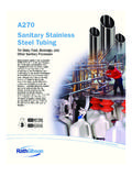
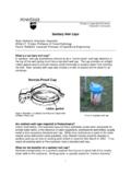
Transcription of Baumann 84000 Sanitary Diaphragm Angle and Inline Control ...
1 84000 Sanitary DiaphragmAngle and Inline Control of Body and Baumann 84000 Sanitary Control valve (figures 1,2, and 3) is designed to satisfy the stringent demandsof the pharmaceutical and biotechnology valves are in compliance with 3-A SanitaryStandards, Inc. of ManualThis instruction manual includes installation,maintenance, and parts information for the Baumann84000 Sanitary Control not install, operate, or maintain Baumann 84000control valves without being fully trained and qualifiedin valve, actuator, and accessory installation,operation, and maintenance. To avoid personal injuryor property damage, it is important to carefully read,understand, and follow all the contents of this manual,including all safety cautions and warnings.
2 If you haveany questions about these instructions, contact yourEmerson sales office or Local Business Partner 1. 84000 Inline Sanitary Valve with Baumann32 ActuatorW9838 Figure 2. 84000 Angle Sanitary Valve with Baumann32 Actuator and FIELDVUEt DVC2000 Digital ValveControllerW9839 Figure 3. 84000 Angle Sanitary Valve with Baumann54 Actuator and FIELDVUE DVC6000 Digital ValveControllerW9840 Instruction ManualD103370X01284000 ValveJune 2017 Instruction ManualD103370X01284000 ValveJune 20172 WARNINGA lways wear protective gloves, clothing and eyewear when performing any installation operations to avoid injury or property damage caused by sudden release of pressure or bursting of pressure retaining parts may resultif service conditions exceed those for which the product was intended.
3 To avoid injury or damage, provide a relief valve forover pressure protection as required by government or accepted industry codes and good engineering with your process or safety engineer for any additional measures that must be taken to protect against installing into an existing application, also refer to the WARNING at the beginning of the Maintenance section in thisinstruction valve is intended for a specific range of pressures, temperatures and other application specifications. Applyingdifferent pressures and temperatures to the valve could result in parts damage, malfunction of the Control valve or loss ofcontrol of the process. Do not expose this product to service conditions or variables other than those for which the productwas intended.
4 If you are not sure what these conditions are you should contact your Emerson sales office or Local BusinessPartner for more complete specifications. Provide the product serial numbers (shown on the nameplate) and all otherpertinent information. WARNINGIf you move or work on an actuator installed on a valve with loading pressure applied, keep your hands and tools awayfrom the stem travel path to avoid personal injury. Be especially careful when removing the stem connector to release allloading on the actuator stem whether it be from air pressure on the Diaphragm or compression in the actuator take similar care when adjusting or removing any optional travel stop. Refer to the relevant actuator hoisting the valve, take care to prevent people from being injured in case the hoist or rigging slips.
5 Be sure to useadequate sized hoists and chains or slings to handle the valve. WARNINGP ersonal injury could result from packing leakage. Valve packing is tightened before shipment; however, the packingmight require some readjustment to meet specific service WARNINGA void personal injury and property damage from sudden release of process pressure or bursting of parts. Beforeperforming any maintenance operations:Instruction ManualD103370X01284000 ValveJune 20173D Do not remove the actuator from the valve while the valve is still Always wear protective gloves, clothing, and eyewear when performing any maintenance Disconnect any operating lines providing air pressure, electric power, or a Control signal to the actuator.
6 Be sure theactuator cannot suddenly open or close the Use bypass valves or completely shut off the process to isolate the valve from process pressure. Relieve process pressureon both sides of the valve. Drain the process media from both sides of the Depending on the actuator construction, it will be necessary to manage the pneumatic actuator springpre-compression. It is essential to refer to the relevant actuator instructions in this manual to perform safe removal ofthe actuator from the Use lock out procedures to be sure the above measures stay in effect while you work on the The valve packing box may contain process fluids that are pressurized, even when the valve has been removed from thepipeline.
7 Process fluids may spray out under pressure when removing the packing hardware or packing rings, or whenloosening the packing box pipe Check with your process or safety engineer for any additional measures that must be taken to protect against a gasket seal is disturbed by removing or shifting gasketed parts, install a new gasket during reassembly. This provides agood gasket seal because the used gasket may not seal DirectionThe preferred flow direction for self-draining is shown in figures 8 and Before installing the valve in the pipeline, thoroughly clean the line of all dirt, welding chips, scale, oil or grease, andother foreign material. A micron size filter is recommended upstream of the Install valve so that the controlled fluid will flow through the valve body in the direction selected in figures 8 and leak detection port should be located at the lowest point in the installed A three-valve bypass must be used to permit removal of the Control valve from the line without shutting down To detect if leakage or breakage of the Diaphragm has occurred, a pressure gauge may be installed in the 1/8 NPTport (key 14) in the bonnet, see figures 4, 5, and 6.
8 WARNINGTo avoid personal injury or property damage, do not attempt to do any work on a valve while the system is in operation,the valve must be isolated 100% from the active system and the isolated line voided of pressure and/or hazardous Piping1. For an air-to-extend actuator (air-to-close action), connect the actuating air pressure line to the 1/4 NPT opening inthe upper Diaphragm case. For an air-to-retract actuator (air-to-open action) connect the actuating air pressure lineto the 1/4 NPT in the lower Diaphragm ManualD103370X01284000 ValveJune 201742. Use mm (1/4 inch) tubing or equivalent for all air lines. If the air line exceeds 8 m (25 ft) in length, mm(3/8 inch) tubing is preferred.
9 Air lines must not leak. Air pressure should not exceed bar (35 psig).Valve Body RemovalReference figures 4, 5, and 6. (Not Required For Actuator Reversal)For field replacement of the Diaphragm (key 8), follow steps 1 through 4 not squeeze the valve body in a For fail-closed action (air-to-open), stroke the actuator up to take pressure off from the Diaphragm pushing againstseat. For fail-open action (air-to-close), there is no need to stroke Remove the bonnet screws (key 18) for NPS 1 valves or the clamp (key 11) for NPS 1-1/2 or 2 Lift the bonnet assembly (key 2) with the actuator from the valve body (key 1).4. Once disassembled; for fail-closed action ONLY, release pressure from the actuator to be able to unscrew thediaphragm, for fail-open action you must pressurize the actuator to unscrew the Diaphragm .
10 This is the only actionrequired for inspection or Stroke the actuator down to exert some pressure and remove the Diaphragm (key 8) by unscrewing the Diaphragm (key 8) from the compressor (key 5). Remove the bonnet O-ring (key 15) (NPS 1-1/2 and 2 valves only). Wipe thediaphragm (key 8) with a clean soft cloth and examine for Inspect the valve body sealing surfaces. If valve leakage becomes excessive, replacement of the Diaphragm (key 8)may be RemovalTo remove the actuator, unscrew the drive nut (key 9) and loosen the jam nuts (key 27). Unscrew the piston stem (key 3) from the actuator personal injury or property damage from sudden release of pressure or bursting of parts.