Transcription of BETRIEBSANLEITUNG FÜR …
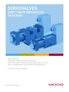
1 OPERATING INSTRUCTIONS FORPROPORTIONAL VALVESD633K, D634K AND D635K SERIESISO 4401 SIZE 03 AND 05 BETRIEBSANLEITUNG F RPROPORTIONALVENTILEBAUREIHEN D633K, D634K UND D635 KISO 4401 GR SSEN 03 UND 05 PROPORTIONAL control valves WITH INTEGRATED ELECTRONICS EXPLOSION PROTECTEDPROPORTIONALVENTILE MIT INTEGRIERTER ELEKTRONIKIN EXPLOSIONSGESCH TZTER AUSF HRUNGWHAT MOVES YOUR WORLDRev. H, January 2014 Rev. H, Januar 2014 OPERATING INSTRUCTIONS FORPROPORTIONAL VALVESD633K, D634K AND D635K SERIESISO 4401 SIZE 03 AND 05 PROPORTIONAL control valves WITH INTEGRATED ELECTRONICS EXPLOSION PROTECTEDWHAT MOVES YOUR WORLDRev. H, January 2014 2 Rev. H, January 2014 moog Proportional valves D633K, D634K and D635K SeriesWhenever the highest levels of motion controlperformance and design fl exibility are required, you ll fi ndMoog expertise at work.
2 Through collaboration, creativityand world-class technological solutions, we help youovercome your toughest engineering obstacles. Enhanceyour machine s performance. And help take your thinkingfurther than you ever thought catalog is for users with technical knowledge. To ensure all necessary characteristics for function and safety of the system, the user has to check the suitability of the products described herein. The products described in this document are subject to change without notice. In case of doubt, please contact moog . moog is a registered trademark of moog Inc. and its subsidiaries. All trademarks as indicated herein are the property of moog Inc. and its subsidiaries. For the full disclaimer refer to the most current information, visit or contact your local moog offi .. 3 Safety Instructions .. 3 DESCRIPTION .. 5 Principle and Function.
3 5 Technical Data .. 7 Name Plates .. 8 INSTALLATION .. 9 General Informations .. 9 Venting of Pressure Transducer at D635K ..13 Setting Up .. 14 Declaration of Conformity .. 14 FAULTS AND MAINTENANCE ..15 ACCESSOIRES ..16 APPENDIX ..17 CONTACT ..19 INTRODUCTION3 Rev. H, January 2014 moog Proportional valves D633K, D634K and D635K SeriesWarnings and symbolsRefers to special orders and prohibitions to prevent to special orders and prohibitions to prevent injury or property application1. The valves series D633K, D634K and D635K are electrical equipment for hazardous areas, type of protection de (d Flameproof enclosure to IEC 60079-1 and EN 60079-1, e Increased safety to IEC 60079-7 and EN 60079-7).Identifi cation D633K/D635K SeriesApprovalBVS 07 ATEX E 006 X, 0123 IECEx BVS cationII 2G Ex de II B+H2 T4 G bTemperature rangeAmbient -20 to +60 C (-4 to +140 F)Fluid -20 to +60 C (-4 to +140 F)Alternative allowed.
4 Identifi cationII 2G Ex de II B+H2 T3 GbTemperature rangeAmbient -20 to +60 C (-4 to +140 F)Fluid -20 to +80 C (-4 to +176 F)Identifi cation D634K-R SeriesApprovalBVS 07 ATEX E 006 X, 0123 IECEx BVS cationII 2G Ex de II B+H2 T3 GbTemperature rangeAmbient -20 to +60 C (-4 to +140 F)Fluid -20 to +70 C (-4 to +158 F)Identifi cation D634K-P SeriesApprovalBVS 07 ATEX E 006 X, 0123 IECEx BVS cationII 2G Ex de II B+H2 T3 GbTemperature rangeAmbient -20 to +60 C (-4 to +140 F)Fluid -20 to +80 C (-4 to +176 F)Identifi cation D634K-P SeriesApprovalBVS 07 ATEX E 006 X, 0123 IECEx BVS cationII 2G Ex de II B+H2 T4 G bTemperature rangeAmbient -20 to +60 C (-4 to +140 F)Fluid -20 to +65 C (-4 to +149 F)Identifi cation D634K-P SeriesApprovalBVS 07 ATEX E 006 X, 0123 IECEx BVS cationII 2G Ex de II B+H2 T5 GbTemperature rangeAmbient -20 to +35 C (-4 to +95 F)Fluid -20 to +35 C (-4 to +95 F)2.
5 The valves are proportional valves intended for direc tional -, velocity-, pressure- and force control in hydraulic control systems that operate with mineral oil based fl uids. Others on request. Using the valves for purposes other than those mentioned above is considered contrary to the intended use. The user bears entirely the risk of such misuse. Correct application involves also observing the operating instruction and complying with the inspection and maintenance directives. Organizational measures1. We recommend to include this operating instruction into the maintenance plan of the In addition to the operating instruction, observe also all other generally applicable legal and other mandatory regulations relevant to accident prevention and environmental protection. Instruct the operator All safety and danger prevention instructions of the machine/plant must meet the requirements of EN 982, IEC 60079-0 and EN and qualifi cation of personnelService work carried out by the user on explosion protection valves is prohibited, as intervention by third parties renders the explosion protection permit null and SAFETY INSTRUCTIONSATTENTIONDANGERDANGERATTENTI ONATTENTION4 Rev.
6 H, January 2014 moog Proportional valves D633K, D634K and D635K SeriesINSTRUCTIONSSAFETY INSTRUCTIONSFor specifi c operational phases1. Take the necessary precautions to ensure that the valve is used only when in a safe and reliable Check the valve at least once per working shift for obvious damage and defects ( leakage or damaged cables). Report any changes to the responsible group/person immediately. If necessary, stop the machine immediately and secure Before working on the valves or the machine, shut down and switch off the machine without fail and de-energize and depressurize the In the event of malfunctions, stop the machine/plant immediately and secure it. Have any defects rectifi ed If the machine/plant is completely shut down for maintenance and repair work at the valve, it must be secured against inadvertent start up by: Locking the principal control elements and removing the key Attaching a warning sign to the main switch6.
7 Before removing the valve depressurize all system sections to be opened, pressure lines and accumulators of the hydraulic system in accordance with the specifi c instructions for the the operation of hydraulic plants1. Work on electrohydraulic equipment must be carried out only by personnel having special knowledge and experience in electrohydraulic Check all lines, hoses and fi ttings of the plant regularly for leaks and obvious damage. Repair damage immediately. Splashed oil may cause injury and fi The strong magnetic fi elds of the permanent magnet linear force motor can have a disruptive effect on sensitive devices, such as , cardiac pacemakers. This may result in serious personal injuries and serious damage to property. Observe the relevant safe distances appropriate for the Falling objects, such as , valves , tools or accessories, may result in personal injuries and damage to property.
8 Wear suitable safety equipment, such as , safety shoes or valves and hydraulic lines can become very hot during operation. Contact may result in burns. Wear suitable safety equipment, such as , work Depending on the application, signifi cant levels of noise may be generated when the valves are operated. If necessary, the manufacturer and operator of the machine must take appropriate sound insulation measures or stipulate that suitable safety equipment, , ear protection, be When handling oil, grease and other chemical substances, observe safety regulations valid for each product and wear suitable safety equipment, such as , work The connectors, mating connectors and connection cables may be used exclusively for the connection of the valve. Misuse, such as , use as tread or transport fi xture, can cause damage and thus may result in personal injuries as well as further damage to H, January 2014 moog Proportional valves D633K, D634K and D635K SeriesDESCRIPTIONG eneralThe explosion protected valves D633K/D634K Series are direct driven proportional control valves (DDV) with electrical closed loop spool position control .
9 The spool drive is a permanent magnet linear force motor which actively strokes the spool from its spring centred position in both directions. The closed loop spool position electronics and pulse width modulated (PWM) drive electronics are integrated into the valve. This permits control of the valve directly from, for example, a machine control without the use of additional interface functionAn electrical signal corresponding to the desired spool position is applied to the integrated electronics and produces a pulse width modulated (PWM) current in the linear force motor coil. The resulting force causes the spool to move. An oscillator excites the spool position transducer (LVDT), producing an electrical signal proportional to spool position. The demodulated spool position signal is compared with the command signal and the resulting spool position error causes current in the force motor coil until the spool has moved to its commanded position, and the spool position error is reduced to zero.
10 The resulting spool position is thus proportional to the command force motorIntegratedelectronicsPositiontransd ucerSpoolBushingTerminal stripPRINCIPLE AND FUNCTIONQ- valves D633K and D634K6 Rev. H, January 2014 moog Proportional valves D633K, D634K and D635K SeriesDESCRIPTIONG eneralThe explosion protection valve D635K Series consists of direct-controlled proportional pressure control valves with electrical position control of the control permanent magnet linear motor is used for drive, moving (in contrast to proportional magnet drives) the control piston out of the spring-centred central position in both working directions. Pressure control and pulse-width modulation (PWM) drive electronics are integrated in the valve, as is a pressure transducer and setpoint ramp. Triggering of the valve is thus direct ( it can be achieved by the machine control system without any interconnected electronics).