Transcription of Binary Phase Shift Keying (BPSK) Lecture Notes 6: Basic ...
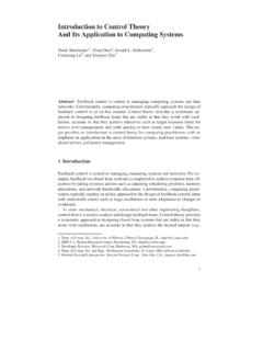
1 Lecture Notes 6: Basic Modulation SchemesIn this Lecture we examine a number of different simple modulation schemes. We examine theimplementation of the optimumreceiver, the error probabilityand the wouldlike the simplest possible receiver, withthe lowest error probabilityand smallestbandwidthfor a given data Binary Phase Shift Keying (BPSK) The first modulation considered is Binary Phase Shift Keying . In this scheme during every bitduration, denoted byT, one of two phases of the carrier is transmitted. These two phases are180 degrees apart. This makes these two waveforms antipodal. Any Binary modulation wherethe two signals are antipodal gives the minimumerror probability(for fixed energy) over anyother set of Binary signals. The error probabilitycan onlybe made smaller (for fixed energyper bit)by allowing more than two waveforms for transmitting BPSKM odulator b t 2 Pcos 2 fct Modulator s t n t r t Figure 33: Modulator for BPSKTo mathematicallydescribed the transmitted signal we define a pulse functionpT t aspT t 1 0 t T0 otherwise.
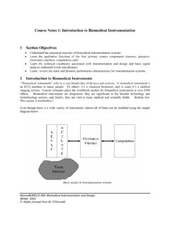
2 T1pT t TLetb t denote the data waveformconsisting of an infinitesequence of pulses of durationTVI-3 and height t l blpT t lT bl 1 1!"The transmitted signal then is given bys t 2P l blcos 2 fct pT t lT 2P b t cos 2 fct 2 Pcos 2 fct t where t is the Phase waveform. The signal power isP. The energy of each transmitted bitisE Phase of a BPSK signal can take on one of two values as shown inFigure b t T2T3T4T5T1-1t t T2T3T4T5T 0tFigure 34: Data and Phasewaveformsfor BPSKVI-5 r t 2 Tcos 2 fct LPF X iT t iT 0 decbi 1 1 0 decbi 1 1 Figure 35: Demodulator for BPSKThe optimumreceiver for BPSK inthe presence of additive whiteGaussian noise is shown inFigure VI-3. The low pass filter (LPF) is a filter matched tothe baseband signal beingtransmitted. For BPSK this is just a rectangular pulse of durationT. The impulse response ish t pT t "The output of the low pass filter isX t 2 Tcos 2 fc h t r d "VI-6 The sampled version of the output is given byX iT 2 Tcos 2 fc pT iT r d iT i 1 T 2 Tcos 2 fc 2P b cos 2 fc n d iT i 1 T2 P T bi 1cos 2 fc cos 2 fc d i" iis Gaussian randomvariable, mean 0 varianceN0 2.
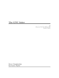
3 Assuming 2 fcT 2 nfor someintegern(or thatfcT 1)X iT PT bi 1 i E bi 1 i"VI-7 X(iT)PPe,+1e,-1EE0 Figure 36: ProbabilityDensityof Decision Statisticfor Binary PhaseShiftKeyingVI-8 Bit Error Probability of BPSKPe b Q 2EN0 Q 2 EbN0 whereQ x x12 e u2 2duFor Binary signals this is the smallest bit error probability, BPSK are optimal signals andthe receiver shown above is optimum(inadditive whiteGaussian noise). For Binary signalsthe energy transmitted per information bitEbis equal tothe energy per signalE. ForPe b 10 5we need a bit-energy,Ebtonoise densityN0ratioofEb N0 9" :Q x is a decreasing function which is 1/2atx 0. There are efficient algorithms (based on Taylorseries expansions) tocalculateQ x . SinceQ x e x2 2 2 the error probabilitycan beupper bounded byPe b 12e Eb N0 which decreases exponentiallywithsignal-to-noise 161412108642010-10 Error Probability of BPSKEb/N0(dB)Pe,b10-910-810-710-610-510- 410-310-210-11 Figure 37: Error Probabilityof Bandwidth of BPSKThe power spectral densityis a measure of the distribution of power withrespect power spectral densityfor BPSK has the formS f PT2 sinc2 f fc T sinc2 f fc T wheresinc x sin x x"Notice that S f d f P"The power spectrumhas zeros or nullsatf fc i Texcept fori 0; that is there is a null atf fc 1 Tcalled the first null;a null atf fc 2 Tcalled the second null;etc.
4 Thebandwidthbetween the first nullsis called the null-to-null bandwidth. For BPSK thenull-to-null bandwidthis 2 T. Notice that the spectrumfallsoff as f fc 2asfmoves awayfromfc. (The spectrumof MSK fallsoff as the fourthpower, versus the second power forBPSK).It is possible toreduce the bandwidthof a BPSK signal by filtering. If the filtering is doneproperlythe (absolute) bandwidthof the signal can be reduced to1 Twithout causing anyintersymbol interference; that is all the power is concentrated inthe frequency rangeVI-11 1 2T f fc 1 2T . The drawbacks are that the signal loses itsconstant envelopeproperty(useful for nonlinear amplifiers) and the sensitivitytotiming errors is greatlyincreased. The timing sensitivityproblemcan be greatlyalleviated by filtering toa slightlylarger bandwidth 1 2T f fc 1 2T .VI-12 (f)-4-3-2-101234(f-fc)TFigure 38: Spectrumof BPSKVI-13 -100-80-60-40-200S(f) (dB)-5-4-3-2-1012345(f-fc)TFigure 39: Spectrumof BPSKVI-14 -100-80-60-40-200S(f) (dB)-10-8-6-4-20246810(f-fc)TFigure 40: Spectrumof BPSKVI-15 ExampleGiven: Noise power spectral densityofN0 2 180 dBm/Hz =10 21 Watts/Hz.
5 Pr 3 10 13 Watts DesiredPe 10 :The data rate that can be used and the bandwidththat is :NeedQ 2Eb N0 10 7orEb N0 11"3dB orEb N0 13"52. ButEb N0 PrT N0 13"52. Thus the data bit must be at leastT 9"0 10 8seconds long, data rate 1 Tmust be less than 11 Mbits/second. Clearlywe also need a (null-to-null)bandwidthof 22 alternative view of BPSK is that of two antipodal signals; that iss0 t E t 0 t Tands1 t E t 0 t Twhere t 2 Tcos 2 fct 0 t Tis a unit energy waveform. The above describesthe signals transmitted onlyduring the interval 0 T . Obviouslythis is repeated for otherVI-16 intervals. The receiver correlates with t over the interval 0 T and compares withathreshold(usually0) tomake a decision. The correlation receiver is shown below. r t t T0 decs0 decs1 This is called the Correlation Receiver. Note that synchronization tothe symbol timing andoscillator Phase are Effect of FilteringandNonlinear Amplificationon a BPSK waveformIn this section we illustrate one maindrawback toBPSK.
6 The fact that the signal amplitudehas discontinuities causes the spectrumtohave fairlylarge sidelobes. For a systemthat has aconstraint on the bandwidththis can be a problem. A possible solution is tofilter the signal. Abandpas filter centered at the carrier frequency which removes the sidbands can be insertedafter mixing tothe carrier frequency. Alternatlywe can filter the data signal at basebandbefore mixing tothe carrier we simulate this type of systemtoillustrate the effect of filtering and nonlinearamplification. The data waveformb t is mixed ontoa carrier. This modulated waveformisdenoted bys1 t 2 Pcos 2 fct The signals1 t is filtered by a fourthorder bandpass Butterworthfilter withpassband fromfc 4 Rbtofc 4 RbThe filtered signal is denoted bys2 t . The signals2 t is then The input-output characteristics of the amplifier ares3 t 100 tanh 2s1 t This amplifier is fairlyclose toa hard limiter inwhich every input greater than zero is mappedto100 and every input less than zero is mapped ParametersSampling Frequency= 50 MHzSampling Time =20nsecondsCenter Frequency= Rate= Time= msVI-19 10 5 1 (t)Data 10 5 2 1012times(t)Signal waveformVI-20 107 180 160 140 120 100 80 60 40frequencyS(f)Signal spectrumVI-21 2 1 100 80 60 40 20020406080100 InputOutputVI-22 107 90 85 80 75 70 65 60 55 50 45 40frequencyS2(f)Filtered signal spectrumVI-23 10 5 1 (t)Data 10 5 2 1012times2(t)Filtered signal waveformVI-24 107 80 70 60 50 40 30 20frequencyS2(f)Amplified and filtered signal spectrumVI-25 10 5 1 (t)Data 10 5 100 50050100times3(t)
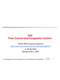
7 Amplified and filtered signal waveformVI-26 Quaternary Phase Shift Keying (QPSK)The next modulation technique we consider is QPSK. In this modulation technique one offour phases of the carrier is transmitted ina symbol duration denoted byTs. Since one of fourwaveforms is transmitted there are two bitsof information transmitted during each symbolduration. An alternative way of describing QPSK is that of two carriers offset inphase by 90degrees. Each of these carriers is then modulated using BPSK. These two carriers are calledthe inphase and quadrature carriers. Because the carriers are 90 degrees offset, at the output ofthe correlation receiver they do not interfer witheach other (assuming perfect phasesynchronization). The advantage of QPSK over BPSK is that the the data rate is twice as highfor the same bandwidth. Alternativelysingle-sideband BPSK wouldhave the same rate inbitsper second per hertz but wouldhave a more difficult job of recovering the carrier frequencyand bs t bc t s t Pcos 2 fct Psin 2 fct Figure 41: Modulator for QPSKVI-28 bc t l bc lpTs t lTs bc l 1 1!
8 Bs t l bs lpTs t lTs bs l 1 1!s t P bc t cos 2 fct bs t sin 2 fct 2 Pcos 2 fct t The transmitted power is stillP. The symbol duration isTsseconds. The data rate isRb 2 Phase t , of the transmitted signal is related tothe data waveformas follows. t l lpTs t lTs l 4 3 4 5 4 7 4!The relation between landbc l bs lis shown inthe following tableVI-29 bc lbs l l+1+1 4-1+13 4-1-15 4+1-17 4VI-30 bc t Ts2Ts3Ts4Ts5Ts1-1tbs t Ts2Ts3Ts4Ts5Ts1-1t t Ts2Ts3Ts4Ts5Ts7 45 43 4 4tFigure 42: Timing and Phaseof QPSKVI-31 The constellation of QPSK is shown below. The Phase of the overall carrier can be on of fourvalues. Transitions between any of the four values may occur at any symbol of this, it is possible that the transition is tothe 180 degree oppositephase. When thishappens the amplitude of the signal goes through zero. In theory this is an instantaneoustransition.
9 In practice, when the signal has been filtered toremove out-of-band componentsthis transition is slowed down. During this transition the amplitude of the carrier goes throguhzero. This can be undesireable for various reasons. One reason is that nonlinear amplifierswitha non constant envelope signal willregenerate the out-of-band spectral reason is that at the receiver, certainsynchronization circuitsneed constant envelopetomaintaintheir tracking (+1,+1)(+1,-1)(-1,-1)(-1,+1)In- Phase ChannelQuadrature-phaseChannelFigure 43: Constellation of QPSKVI-33 The bandwidthof QPSK is given byS f PTs 2 sinc2 f fc Ts sinc2 f fc Ts PTb sinc2 2 f fc Tb sinc2 2 f fc Tb sinceTs Tb 2. Thus whilethe spectrumis compressed by a factor of 2 relative toBPSK withthe same bit rate, the center lobe is also 3dB higher, that is the peak power densityishigher for QPSK than BPSK. The null-to-null bandwidthis 2 Ts (f)-4-3-2-101234(f-fc)TQPSKBPSKF igure 44: Spectrumof QPSKVI-35 -100-80-60-40-200S(f) dB-5-4-3-2-1012345(f-fc)TQPSKBPSKF igure 45: Spectrumof QPSKVI-36 -100-80-60-40-200S(f) dB-10-8-6-4-20246810(f-fc)TQPSKBPSKF igure 46: Spectrumof QPSKVI-37 r t 2 Tscos 2 fct 2 Tssin 2 fct LPFLPF t iTsXs iTs t iTsXc iTs 0 decbs i 1 1 0 decbs i 1 1 0 decbc i 1 1 0 decbc i 1 1 Figure 47.
10 QPSK DemodulatorVI-38 Assuming 2 fcTs 2 nor 2 fcTs 1Xc iTs PTs 2bc i 1 c i Ebbc i 1 c iXs iTs PTs 2bs i 1 s i Ebbs i 1 s iwhereEb PTs 2 is the energy per transmitted c iand s iare Gaussian randomvariables, withmean 0 and varianceN0 Error Probabilityof QPSKPe b Q 2 EbN0 The probabilitythat a symbol error is made isPe s 1 1 Pe b 2 2Pe b P2e bThus for the same data rate, transmitted power, and bit error rate (probabilityof error), QPSKhas half the (null-to-null)bandwidthof ExampleGiven: Noise power spectral densityofN0 2 110 dBm/Hz =10 14 Watts/Hz. Pr 3 10 6 Watts DesiredPe 10 :The data rate that can be used and the bandwidththat is needed for :NeedQ 2Eb N0 10 7orEb N0 11"3dB orEb N0 13"52. ButEb N0 Pr2 Ts N0 PrT N0 13"52sinceTs 2T. Thus the data bit must be at leastT 9"0 10 8seconds long, the datarate 1 Tmust be less than 11 Mbits/second. Clearlywe also need a (null-to-null)bandwidthof 11 Offset Quaternary Phase Shift Keying (OQPSK)The disadvantages of QPSK can be fixed by offsetting one of the data streams by a fraction(usually1/2) of a symbol duration.