Transcription of Fully-Differential Amplifiers (Rev. E)
1 Application ReportS1 Fully-Differential AmplifiersJames KarkiAAP Precision AnalogABSTRACTD ifferential signaling has been commonly used in audio, data transmission, and telephonesystems for many years because of its inherent resistance to external noise sources. Today,differential signaling is becoming popular in high-speed data acquisition, where the ADC sinputs are differential and a differential amplifier is needed to properly drive other advantages of differential signaling are reduced even-order harmonics andincreased dynamic report focuses on integrated, Fully-Differential Amplifiers , their inherent advantages, andtheir proper use. It is presented in three parts: 1) Fully-Differential amplifier architecture andthe similarities and differences from standard operational Amplifiers , their voltage definitions,and basic signal conditioning circuits; 2) Circuit analysis (including noise analysis), providesa deeper understanding of circuit operation, enabling the designer to go beyond the basics;3) Various application circuits for interfacing to differential ADC inputs, antialias filtering, anddriving transmission.
2 2 What Is an Integrated, Fully-Differential Amplifier?3.. 3 Voltage Definitions5.. 4 Increased Noise Immunity5.. 5 Increased Output Voltage Swing6.. 6 Reduced Even-Order Harmonic Distortion6.. 7 Basic Circuits6.. 8 Circuit Analysis and Block Diagram8.. 9 Noise Analysis13.. 10 Application Circuits15.. 11 Terminating the Input Source15.. 12 Active Antialias Filtering20.. 13 VOCM and ADC Reference and Input Common-Mode Voltages23.. 14 Power Supply Bypass25.. 15 Layout Considerations25.. 16 Using Positive Feedback to Provide Active Termination25.. 17 Conclusion27.. SLOA054E2 Fully-Differential AmplifiersList of Figures1 Integrated Fully-Differential Amplifier vs Standard Operational Amplifier4.. 2 Simplified Fully-Differential Amplifier4.. 3 Fully-Differential Amplifier Voltage Definitions5.. 4 Fully-Differential Amplifier Noise Immunity5.. 5 Differential Output Voltage Swing6.. 6 Amplifying Differential Signals7.. 7 Converting Single-Ended Signals to Differential Signals7.
3 8 Analysis Circuit8.. 9 Block Diagram9.. 10 Single-Ended-to-Differential Amplifier11.. 11 Circuit With 1 = 011.. 12 Circuit With 2 = 012.. 13 Circuit With 2 = 112.. 14 Circuit With 1 = 0 and 2 = 112.. 15 Noise Analysis Circuit13.. 16 Block Diagram of the Amplifier s Input-Referred Noise14.. 17 Terminating a Differential Input Signal16.. 18 Differential Termination Impedance16.. 19 Differential Thevenin Equivalent16.. 20 Differential Solution for Gain = 117.. 21 Terminating a Single-Ended Input Signal17.. 22 Single-Ended Termination AC Impedance18.. 23 Single-Ended Thevenin Equivalent18.. 24 Single-Ended Solution for Gain = 119.. 25 Balance vs Unbalanced Amplifiers20.. 26 First-Order Active Low-Pass Filter21.. 27 First-Order Active Low-Pass Filter With Passive Second Pole21.. 28 Third-Order Low-Pass Filter Driving an ADC22.. 29 1-MHz, Second-Order Butterworth Low-Pass With Real Pole at MHz23.. 30 Internal Reference Circuit of the ADS809 and Recommended Bypass Scheme24.
4 31 VOCM24.. 32 Using Positive Feedback to Provide Active Termination26.. 33 Output Waveforms With Active and Standard Termination27.. SLOA054E3 Fully-Differential Amplifiers1 IntroductionWhy use integrated Fully-Differential Amplifiers ? Increasesd immunity to external noise Increased output voltage swing for a given voltage rail Ideal for low-voltage systems Integrated circuit is easier to use Reduced even-order harmonicsProfessional audio engineers use the term balanced to refer to differential-signal conveys the idea of symmetry, which is very important in differential systems. The driverhas balanced outputs, the line has balanced characteristics, and the receiver has are two methods commonly used to manipulate differential signals: electronic andtransformer. Electronic methods have advantages, such as lower cost, small size and weight, and widebandwidth. Transformers offer very good CMRR vs frequency, galvanic isolation, no power consumption(efficiencies near 100%), and immunity to very-hostile EMC report focuses on electronic methods for signal conditioning differential signals usingintegrated, Fully-Differential Amplifiers such as the THS41xx and THS45xx families ofhigh-speed Amplifiers from Texas Is an Integrated, Fully-Differential Amplifier?
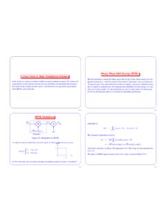
5 An integrated, Fully-Differential amplifier is very similar in architecture to a standard, voltage-feedback operational amplifier, with a few differences as illustrated in Figure 1. Both types ofamplifiers have differential inputs. Fully differential Amplifiers have differential outputs, while astandard operational amplifier s output is single-ended. In a Fully-Differential amplifier, the outputis differential and the output common-mode voltage can be controlled independently of thedifferential voltage. The purpose of the Vocm input in the Fully-Differential amplifier is to set theoutput common-mode voltage. In a standard operational amplifier with single-ended output, theoutput common-mode voltage and the signal are the same thing. There is typically one feedbackpath from the output to the negative input in a standard operational amplifier. A fully-differentialamplifier has multiple feedback paths, which is discussed in detail in this Amplifiers + _+VIN VIN+VOUT+VOUT + VIN VIN+VOUTVOCMF ully-Differential AmplifierStandard Operational AmplifierFULLY-DIFFERENTIAL AMPLIFIERSTANDARD OPERATIONAL AMPLIFIERD ifferential inDifferential inDifferential outSingle-ended outOutput common-mode voltage set by VocmOutput common-mode voltage is signalMultiple feedback pathsSingle feedback pathFigure 1.
6 Integrated Fully-Differential Amplifier vs Standard Operational AmplifierFigure 2 shows a simplified version of an integrated, Fully-Differential amplifier (representative ofthe THS41xx or the THS45xx). Q1 and Q2 are the input differential pair. In a standardoperational amplifier, output current is taken from only one side of the input differential pair andused to develop a single-ended output voltage. In a Fully-Differential amplifier, currents from bothsides are used to develop voltages at the high-impedance nodes formed at the collectors ofQ3/Q5 and Q4/Q6. These voltages are then buffered to the differential outputs OUT+ and OUT .At first analysis, voltage common to IN+ and IN does not produce a change in the current flowthrough Q1 or Q2 and thus produces no output voltage it is rejected. The output common-mode voltage is not controlled by the input. The Vocm error amplifier maintains the outputcommon-mode voltage at the same voltage applied to the Vocm pin by sampling the outputcommon-mode voltage, comparing it to the voltage at Vocm, and adjusting the internal not connected, Vocm is biased to the midpoint between VCC and VEE by an internal Buffer_+Vocm ErrorAmplifierx1 Output BufferCCQ5Q6 VCCVocmVCCIN IN+VEEOUT+OUT RRFigure 2.
7 Simplified Fully-Differential AmplifierSLOA054E5 Fully-Differential Amplifiers3 Voltage DefinitionsTo understand the behavior of a Fully-Differential amplifier, it is important to understand thevoltage definitions used to describe the amplifier. Figure 3 shows a block diagram used torepresent a Fully-Differential amplifier and its input and output voltage voltage difference between the plus and minus inputs is the input differential voltage, average of the two input voltages is the input common-mode voltage, difference between the voltages at the plus and minus outputs is the output differentialvoltage, Vod. The output common-mode voltage, Voc, is the average of the two output voltages,and is controlled by the voltage at a(f) as the frequency-dependant differential gain of the amplifier, then Vod = Vid a(f).Input voltage definitionOutput voltage definitionTransfer functionOutput common-mode voltageVic+(Vin)))(Vin )2 Vid = (Vin+) (Vin )Vod = (Vout+) (Vout )Vod = Vid a(f)Voc = VocmVoc+(Vout)))(Vout )2+ _+VIN VIN+VOUT+VOUT VOCMVEEVCCa(f)Figure 3.
8 Fully-Differential Amplifier Voltage Definitions4 Increased Noise ImmunityInvariably, when signals are routed from one place to another, noise is coupled into the wiring. Ina differential system, keeping the transport wires as close as possible to one another makes thenoise coupled into the conductors appear as a common-mode voltage. Noise that is common tothe power supplies also appears as a common-mode voltage. Since the differential amplifierrejects common-mode voltages, the system is more immune to external noise. Figure 4illustrates the noise immunity of a Fully-Differential amplifier.+ _+VIN VIN+VOUT+VOUT VOCMVEEVCCD ifferential Structure RejectsCoupled Noise at the InputDifferential Structure RejectsCoupled Noise at the outputDifferential Structure RejectsCoupled Noise at the Power SupplyFigure 4. Fully-Differential Amplifier Noise ImmunitySLOA054E6 Fully-Differential Amplifiers5 Increased Output Voltage SwingDue to the change in phase between the differential outputs, the output voltage swing increasesby a factor of 2 over a single-ended output with the same voltage swing.
9 Figure 5 illustrates makes them ideal for low voltage applications.+ _+VIN VIN+VOUT+VOUT VOCMVEEVCC0+1+10abVOD = 1 0 = 1 VOD = 0 1 = 1 Differential Output Results in VOD p-p = 1 ( 1) = 2 X SE OutputFigure 5. Differential Output Voltage Swing6 Reduced Even-Order Harmonic DistortionExpanding the transfer functions of circuits into a power series is a typical way to quantify thedistortion a generic expansion of the outputs and assuming matched Amplifiers , we get:Vout+ = k1 Vin + k2 Vin2 + k3 Vin3 + .. , andVout = k1( Vin)+ k2( Vin)2 + k3( Vin)3 + .. Taking the differential outputVod = 2k1 Vin + 2k3 Vin3 + .. , where k1, k2 and k3 are quadratic terms gives rise to second-order harmonic distortion, the cubic terms gives rise tothird-order harmonic distortion, and so a Fully-Differential amplifier, the odd-order terms retain their polarity, while the even-orderterms are always positive. When the differential is taken, the even order terms life is not quite this perfect.
10 Lab testing of the THS4141 at 1 MHz shows that the secondharmonic at the output is reduced by approximately 6 dB when measured differentially ascompared to measuring either output single-ended. The third harmonic is unchanged between adifferential and single-ended CircuitsIn a Fully-Differential amplifier, there are two possible feedback paths in the main differentialamplifier, one for each side. This naturally forms two inverting Amplifiers , and invertingtopologies are easily adapted to Fully-Differential Amplifiers . Figure 6 shows how to configure afully-differential amplifier with negative feedback to control the gain and maintain a in the two feedback paths is important to have good CMRR performance. CMRR isdirectly proportional to the resistor matching error a error results in 60 dB of Fully-Differential AmplifiersThe Vocm error amplifier is independent of the main differential amplifier. The action of the Vocmerror amplifier is to maintain the output common-mode voltage at the same level as the voltageinput to the Vocm pin.