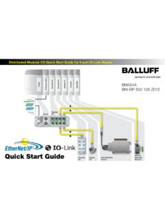
Transcription of BNI EIP-104-105-Z015 E - Balluff
1 bni eip -104-105-Z015IP67 Modules16 InputsUser s Guide 1 Content 1 Notes 3 About this guide 3 Structure of the guide 3 Typographical Conventions 3 Enumerations 3 Actions 3 Syntax 3 Cross-references 3 Symbols 3 Abbreviations 3 2 Safety 4 Intended use 4 General safety notes 4 Meaning of the warnings 4 3 Getting Started 5 Modul overview 5 Mechanical connection 6 Electrical connection 6 Power Supply 6 Grounding 6 Ethernet IP Interface 6 I/O-Port 7 4 Technical data 8 Dimensions 8 Mechanical data 8 Operating conditions 8 Electrical data 8 Ethernet 9 Function indicators 9 Modul status 9 Port 9 5 Integration 10 Data Configuration 10 6 Process Data 11 Process Data Inputs 11 Standard Input Data 11 Process Data Outputs 12 Standard Output Data 12 7 Display 13 General 13 Adress Defaults 13 Controls and visualization 13 Display information 13 Design and Symbols 14 Startup 14 Main Menue 14 IP Setup 15 IP Config 15 Module information 16 General Informations 16 Balluff Network Interface EtherNet/IP , BNI EIP-104-105-Z015 2 8 Webserver 17 General 17 Home 17 Diagnostic Process 17 Diagnostic Module 17 Configurations 17 9 Appendix 18 Included material 18 Ordercode 18 Order Information 18 3 1 Notes About this guide The BNI serves as a decentralized input module for connecting to an EtherNet/IP network.
2 Structure of the guide The guide is organized so that the chapters build on one another. Chapter 2: Basic safety information. Chapter 3: The main steps for installing the device. Chapter 4: Technical data for the device Chapter 5: Integration Chapter 6: Process data Chapter 7: Display Chapter 8: Webserver Chapter 9:Appendix Typographical Conventions The following typographical conventions are used in this Guide. Enumerations Enumerations are shown in list form with bullet points. Entry 1, Entry 2. Actions Action instructions are indicated by a preceding triangle. The result of an action is indicated by an arrow. Action instruction 1. Action result. Action instruction 2. Procedures can also be shown as numbers in brackets. (1) Step no. 1 (2) Step no. 2 Syntax Numbers: Decimal numbers are shown without additional indicators ( 123), Hexadecimal numbers are shown with the additional indicator hex ( 00hex) or with the prefix 0x ( 0x00) Cross-references Cross references indicate where additional information on the topic can be found (see chapter 4 Technical Data ).
3 Symbols Note tip This symbol indicates general notes. Note This symbol indicates a security notice which most be observed. Abbreviations BNI Balluff Network Interface I Standard input port EIP EtherNet/IP EMC Electromagnetic Compatibility FE Function ground O Standard output port Balluff Network Interface EtherNet/IP , BNI EIP-104-105-Z015 4 2 Safety Intended use This guide describes The BNI serves as a decentralized input module for connecting to an EtherNet/IP network. General safety notes Installation and startup are to be performed only by trained specialists. Any damage resulting from unauthorized manipulation or improper use voids the manufacturer s guarantee and warranty. The device is in accordance with EMC Class A. Such equipment may generate RF noise. The operator must take precautionary measures accordingly.
4 The device must be powered only using an approved power supply (see chapter 4 Technical data ). Only approved cable may be used. Operating and testing The operator is responsible for observing local prevailing safety regulations. When defects and non-clearable faults in the device occur, take it out of service and secure against unauthorized use. Approved use in ensured only when the housing is fully installed. Meaning of the warnings Note! The pictogram used with word Caution warns of a possible hazardous situation affecting the health of persons or equipment damage. Ignoring these warnings can result in injury or equipment damage. Always observe the described measures for preventing this danger. 5 3 Getting Started Modul overview Figure Overview bni eip -104-100-Z016 1 Mounting hole 2 EtherNet/IP port 2 3 Display 4 Status LED: Communication / Module 5 Port 5 (Standard Input) 6 Pin/Port LED : Signal status 7 Port 6 (Standard Input) 8 Port 7 (Standard Input) 9 Port 8 (Standard Input) 10 Port 4 (Standard Input) 11 Port 3 (Standard Input) 12 Port 2 (Standard Input) 13 Port 1 (Standard Input) 14 Power Supply Port 15 Label 16 EtherNet/IP port 1 17 Grounding connection 1 5 2 3 11 10 12 13 14 17 7 9 6 8 16 15 4 Balluff Network Interface EtherNet/IP , BNI EIP-104-105-Z015 6 3 Getting Started Mechanical connection The module is attached using 2 M6 screws and 2 washers.
5 Isolation pad as accessory available Electrical connection Power Supply Pin Function Description 1 +24 V Output Power 2 +24 V Input Power 3 0 V Input Power Common GND 4 0 V Output Power Common GND Note Provide sensor/bus power and actuator power from separate power sources if possible. Total current <9A. The total current of all modules may not exceed 9A even when daisy chaining the actuator supply. Grounding Note! The FE connection from the housing to the machine must be low-impedance and kept as short as possible. Ethernet IP Interface M12, D-coded, female Pin Function 1 Tx+ 2 Rx+ 3 Tx- 4 Rx- 7 3 Getting Started I/O-Port M12, A-coded, female Pin Function 1 +24V, 200mA 2 Input 3 GND 4 Input 5 FE Note! For the digital sensor inputs follow the input guideline per EN61131-2, type 2. Note! Unused Input port socket must be fitted with cover caps to ensure IP67 protection rating.
6 Balluff Network Interface EtherNet/IP , BNI EIP-104-105-Z015 8 4 Technical data Dimensions Mechanical data Housing material Die case zinc, matt nickel plated Enclosure rating per IEC 60529 IP 67 (only when plugged-in and threaded-in) Supply voltage 7/8 4-pin male Input ports M12, A-coded (8 x female) Dimensions (W x H x D in mm) 68 x 224 x Mounting type 2-hole screw mount Ground strap attachment M4 Weight Approx. 670 gr. Operating conditions Operating temperature Ta Storage temperature -5 C .. 70 C -25 C .. 70 C EMC - EN 61000-4-2/3/4/5/6 - EN 55011 - Severity level 2B/3A/4B/2B/3A - , CL. B Shock/vibration EN 60068-2-6, EN 60068-2-27 EN 60068-2-29, EN 60068-2-64 Electrical data Supply voltage V DC, per EN 61131-2 Ripple <1% Input current at 24 V 130 mA 9 4 Technical data Ethernet Ethernet IP port 1 x 10 Base-/100 Base-Tx Connection for Ethernet IP port M12, D-coded Cable types per IEEE Shielded twisted pair min.
7 STP CAT 5/ STP CAT 5e Data transmission rate 10/100 Mbit/s Max. cable length 100 m Flow control Half Duplex/Full Duplex (IEEE ) Function indicators Modul status LED Anzeige Funktion green Output power OK UA red Low Output power (< 18V) green Input power OK US red Low Input power (<18V) green flashing Wrong or no configuration on module green Modul operating red flashing Fixed busclock is not possible Mod red-green flashing Initial sequence off Module got no IP address green flashing Module got IP, but no connection could be established green Connection established red flashing Connection timeout Net red-green flashing Initial sequence off Bus clock: 10 Mbit/s 100 yellow Bus clock: 100 Mbit/s LNK green Data transfer Port Each Port has two two-colour LEDs to indidcate the I/O-States. Anzeige Funktion Bemerkung off Input-State State of the Input Pin is 0 yellow Input-State State of the Input Pin is 1 I/O Port red Short-circuit both LEDs: Short-circuit between Pin 1 and 3 or Short-circuit on both output pins Status LEDs: Modul status Port/Pin LEDs: Status of input ports Balluff Network Interface EtherNet/IP , BNI EIP-104-105-Z015 10 5 Integration Data Configuration Please enter the following values to your Control System.
8 They describe the datasizes for input and output data. Instance ID Data length INPUT 100 6 OUTPUT 101 2 11 6 Process Data Process Data Inputs There are 6 bytes of Input data. Have a look at the tables below to see the mapping of the process data inputs. Byte Modul part Description Standard Input ports Process data inputs on standard Inputs Standard Input Data Bit Byte 7 6 5 4 3 2 1 0 Description 0 I32 I34 I22 I24 I12 I14 I02 I04 1 I72 I74 I62 I64 I52 I54 I42 I44 Input data I04 Input on port 0 pin 4 2 S3 S2 S1 S0 3 S7 S6 S5 S4 Short circuit status Short circuit between Pin 1 and 3 on stated port 4 0 0 0 0 0 0 PS 0 Power status PS: Sensor power 5 0 0 0 0 0 0 0 0 Reserved Balluff Network Interface EtherNet/IP , BNI EIP-104-105-Z015 12 6 Process Data Process Data Outputs There are 2 bytes of output data.
9 Have a look at the tables below to see the mapping of the process data outputs. Byte Modul part Description Display Display control Standard Output Data Bit Byte 7 6 5 4 3 2 1 0 Description 0 0 0 0 0 0 0 0 0 Reserved 1 0 0 0 0 0 DL GO RO Display Control DL: Display lock / PLC lock GO: Green LED on Display on RO: Red LED on Display on 13 7 Display General With the implemented display, the address is set directly on the BNI devices. The following address types are implemented: IP address Subnet mask Gateway address. Each address type consists of 4 octets. Additional the display shows information about the hard- and firmwarerevision. There is a lock function fort he display which can be activated out of the control system. If the lock is set editing isn t possible anymore (see Bit layout, chapter 8 Appendix ).
10 Adress Defaults IP Address: Subnetmask: Gatewayaddress: Controls and visualization 1 Display 2 Arrow-Key 3 Octett-Cursor 4 Address type cursor 5 Set -Key 6 LED Display information IP: IP address SN: Subnet address GW: Gateway address 3: fourth octet 2: third octet 1: second octet 0: first octet S IPSNGW3 2 1 01 2 3 4 5 6 2 3 1 0 Cursor for selecting address type Cursor zur Auswahl der Adressauspr gung Cursor for selecting octet IP SNIP GW Balluff Network Interface EtherNet/IP , BNI EIP-104-105-Z015 14 7 Display Design and Symbols There are some symbols used in the following flow-charts to describe the display-functionality: Startup Main Menue Scolling in main meue with short-time keypress on set-key Step in menue with short-time keypress on arrow-key IP 192.