Transcription of BOLTED CONNECTIONS – I
1 BOLTED CONNECTIONS I. BOLTED CONNECTIONS I. 33. INTRODUCTION. CONNECTIONS form an important part of any structure and are designed more conservatively than members. This is because, CONNECTIONS are more complex than members to analyse, and the discrepancy between analysis and actual behaviour is large. Further, in case of overloading, we prefer the failure confined to an individual member rather than in CONNECTIONS , which could affect many members. CONNECTIONS account for more than half the cost of structural steelwork and so their design and detailing are of primary importance for the economy of the structure. The type of connection designed has an influence on member design and so must be decided even prior to the design of the structural system and design of members. For example, in the design of BOLTED tension members, the net area is calculated assuming a suitable number and diameter of bolts based on experience.
2 Therefore, it is necessary to verify the net area after designing the connection . Similarly in the analysis of frames, the member forces are determined by assuming the CONNECTIONS to be pinned, rigid, or semi- rigid, as the actual behaviour cannot be precisely defined. Just as members are classified as bending members or axially loaded members depending on the dominant force/moment resisted, CONNECTIONS are also classified into idealised types while designing. But the actual behaviour of the connection may be different and this point should always be kept in mind so that the connection designed does not differ significantly from the intended type. Take for example, the connection of an axially loaded truss member at a joint. If the truss is assumed to be pin jointed, then the member should ideally be connected by means of a single pin or bolt.
3 However, in practice, if the pin or bolt diameter works out to be larger than that possible, more than one bolt will be used. The truss can then be considered pin-jointed only if the bending due to self-weight or other superimposed loads is negligible. Note that the connection behaviour will also influence the calculation of the effective length for the buckling analysis of struts. The CONNECTIONS provided in steel structures can be classified as 1) riveted 2) BOLTED and 3) welded CONNECTIONS . Riveted CONNECTIONS were once very popular and are still used in some cases but will gradually be replaced by BOLTED CONNECTIONS . This is due to the low strength of rivets, higher installation costs and the inherent inefficiency of the connection . Welded CONNECTIONS have the advantage that no holes need to be drilled in the member and consequently have higher efficiencies.
4 However, welding in the field may be difficult, costly, and time consuming. Welded CONNECTIONS are also susceptible to failure by cracking under repeated cyclic loads due to fatigue which may be due to working loads such as trains passing over a bridge (high-cycle fatigue) or earthquakes (low-cycle fatigue). A special type of BOLTED connection using High Strength Friction Grip (HSFG). Version II 33 - 1. BOLTED CONNECTIONS I. Copyright reserved bolts has been found to perform better under such conditions than the conventional black bolts used to resist predominantly static loading. BOLTED CONNECTIONS are also easy to inspect and replace. The choice of using a particular type of connection is entirely that of the designer and he should take his decision based on a good understanding of the connection behaviour, economy and speed of construction.
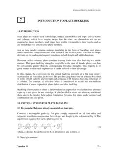
5 In this chapter, the different types of bolts and BOLTED CONNECTIONS used in steel structures are introduced. The scope of the present chapter is limited to BOLTED CONNECTIONS used in tension and compression members as well as in hangers. BOLTED CONNECTIONS , which resist moments and CONNECTIONS between structural members, will be covered in the next chapter. BOLTED CONNECTIONS . CONNECTIONS can also be classified in the following ways: (a) Classification based on the type of resultant force transferred: The BOLTED CONNECTIONS are referred to as concentric CONNECTIONS (force transfer in tension and compression member), eccentric CONNECTIONS (in reaction transferring brackets) or moment resisting CONNECTIONS (in beam to column CONNECTIONS in frames). Ideal concentric CONNECTIONS should have only one bolt passing through all the members meeting at a joint [Fig.]
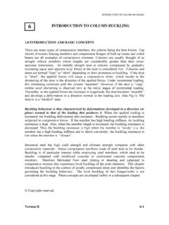
6 1(a)]. However, in practice, this is not usually possible and so it is only ensured that the centroidal axes of the members meet at one point [See Fig. 1(b)]. (a) (b). Fig. 1 Concentric CONNECTIONS The Moment CONNECTIONS are more complex to analyse compared to the above two types and are shown in Fig. 2(a) and Fig. 2(b). The connection in Fig. 2(a) is also known as bracket connection and the resistance is only through shear in the bolts. The connection shown in Fig. 2(b) is often found in moment resisting frames where the beam moment is transferred to the column. The connection is also used at the base of the column where a base plate is connected to the foundation by means of anchor bolts. In this connection , the bolts are subjected to a combination of shear and axial tension. Moment resisting CONNECTIONS will be dealt with in the next chapter.
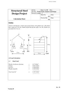
7 Version II 33 - 2. BOLTED CONNECTIONS I. (a) (b). Fig. 2 Moment CONNECTIONS (b) Classification based on the type of force experienced by the bolts: The BOLTED CONNECTIONS can also be classified based on geometry and loading conditions into three types namely, shear CONNECTIONS , tension CONNECTIONS and combined shear and tension CONNECTIONS . Typical shear CONNECTIONS occur as a lap or a butt joint used in the tension members [See Fig. 3]. While the lap joint has a tendency to bend so that the forces tend to become collinear, the butt joint requires cover plates. Since the load acts in the plane of the plates, the load transmission at the joint will ultimately be through shearing forces in the bolts. In the case of lap joint or a single cover plate butt joint, there is only one shearing plane, and so the bolts are said to be in single shear.
8 In the case of double cover butt joint, there are two shearing planes and so the bolts will be in double shear. It should be noted that the single cover type butt joint is nothing but lap joints in series and also bends so that the centre of the cover plate becomes collinear with the forces. (a) Lap connection (b) Butt connection Fig. 3 Shear CONNECTIONS A hanger connection is shown in Fig. 4(a). In this connection , load transmission is by pure tension in the bolts. In the connection shown in Fig. 4(b), the bolts are subjected to both tension and shear. (c) Classification based on force transfer mechanism by bolts: The BOLTED CONNECTIONS are classified as bearing type (bolts bear against the holes to transfer the force) or friction Version II 33 - 3. BOLTED CONNECTIONS I. type (force transfer between the plates due to the clamping force generated by the pre.)
9 Tensioning of the bolts). The force transfer in either case is discussed in more detail later. Support (a) (b). Fig. 4 (a) Tension connection (b) Tension plus Shear connection BOLTS AND BOLTING. Bolts used in steel structures are of three types: 1) Black Bolts, 2) Turned and Fitted Bolts and 3) High Strength Friction Grip (HSFG) Bolts. The International Standards Organisation designation for bolts, also followed in India, is given by Grade In this nomenclature, x indicates one-tenth of the minimum ultimate tensile strength of the bolt in kgf/mm2 and the second number, y, indicates one-tenth of the ratio of the yield stress to ultimate stress, expressed as a percentage. Thus, for example, grade bolt will have a minimum ultimate strength 40 kgf/mm2 (392 Mpa). and minimum yield strength of times 40, which is 24 kgf/mm2 (235 Mpa).
10 Black bolts are unfinished and are made of mild steel and are usually of Grade Black bolts have adequate strength and ductility when used properly; but while tightening the nut snug tight ( Snug tight is defined as the tightness that exists when all plies in a joint are in firm contact) will twist off easily if tightened too much. Turned and- fitted bolts have uniform shanks and are inserted in close tolerance drilled holes and made snug tight by box spanners. The diameter of the hole is about to mm larger than the bolt diameter for ease in fitting. High strength black bolts (grade ) may also be used in CONNECTIONS in which the bolts are tightened snug fit. In these bearing type of CONNECTIONS , the plates are in firm contact but may slip under loading until the hole surface bears against the bolt.