Transcription of Broaches - Basic characteristic - Bianco Gianfranco
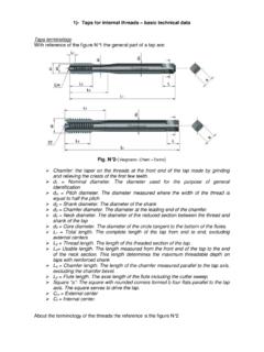
1 Broaches The Basic characteristic Broaches handle mass production with high accuracy and high efficiency. It is very important to point out that complex shapes can be steadily produced without requiring special skills. Broaches are widely used for small batches production or wide variety of products as well. The most important characteristic of broaching operation are: Extremely short machining time with high accuracy Easy machining of the same complex shapes in the axis direction No special skill are required, since machining condition such as depth of cut per tooth or the total amount of cutting are decided when designed and manufactured Fine finish surface, and high accuracy of size Workpiece is fixed by pressure when cutting Parts names There are many types of Broaches , but basically the Broaches for internals have the same characteristic elements. The figure N 1 shows a typical broach with the following part names: Fig. N 1. 1)- Pull end (shank). 2)- Retriever (rear shank). 3)- Chamfer of front pilot 4)- Front pilot 5)- Active part (with cutting teeth).
2 6)- Rear pilot Design of an internal broach is determined by the specification of the broaching machine: shape and size of grip part, pulling out capacity, length that can manage by stroke length, the shape and size of the workpiece to be processed. The shank and the rear shank length must be designed in according with the machine characteristic . The front pilot (entry guide) must be longer than the length of the workpiece in order to always correctly guide the tooth that first cut into the material. This is to be added to the cutting length when there is a recess in the middle or on the processing standard surface of the workpiece to be machined. Standard width allowance of pre-broaching hole diameter is 0,05 mm, but it's better to link this value both to outside diameter of the broach and to the accuracy of pre-broaching bore (see table N 1 and fig. N 2), in order o reduce the deviation angle . Sometimes it's better to make a double chamfering before the guide diameter in order to facilitate the entry of the workpiece in the guide; see figure N 3.
3 Fig. N 2. 3. 1- Value of a (in mm) for different Diam. and accuracy of the pre-broaching bore Diameter of the bore Bore finished by reamer Bore finished by 2 drill pass Bore finished by 1 drill pass 10 mm 0,02 0,07 0,20. 20 mm 0,03 0,07 0,25. 30 mm 0,03 0,08 0,30. 40 mm 0,04 0,08 0,40. 50 mm 0,04 0,09 0,45. 60 mm 0,04 0,09 0,50. 80 mm 0,05 0,10 0,50. 90 mm 0,05 0,10 0,50. 100 mm 0,06 0,11 0,50.. The deviation angle can be calculated with: =.. There are the best condition when L1 = L V but if the length of the workpiece L is more of 75 mm is enough to have = .. The shapes and the sizes of the pull end (shank) are object of the UNI and DIN. normalization. With reference of figure N 4 there are the following norms numbers: 4-A = UNI 4117 and DIN 1415. 4-B = UNI 4117 and DIN 1415. 4-C = UNI 4120 and DIN 1415. Fig:N 4-D = UNI 8083 and DIN 1417. 4-D = Drummond standard shank 4. The tooth shape The typical tooth of a broach are shown in the fig: N 5. 5. P = Pitch S = Land width H = Tooth depth R = Tooth back radius r = Tooth face radius q = Straight land on tip = Rake angle 1 = Clearance angle = Clearance angle of straight land i = Amount of cut per tooth In according with the pitch there are the number of teeth contemporaneously in contact with the surface of the workpiece.
4 The minimum number of teeth in contact must be 2 3, but the maximum cannot be more of 6 7. The value of the pitch can be calculate with the following formula: = . Where K is a coefficient and L is the length of the bore. The value of the K is: For steel: K = 1,8. For bronze K = 1,7. For cast iron K = 1,6. For the finishing teeth the value of K must multiply for 0,87. If the length of the workpiece divided by the pitch is an integer number maybe during the cutting operation there are some vibrations. Irregular pitch it's applied to avoid resonating of cutting vibration. Especially in round Broaches , it's effective for undulations and accuracy on the processing surface. For irregular pitch add or take 0,5 to 1,0 mm to or from the standard pitch. Another very important element is the value of H, the tooth depth. From this value depends the capacity of the chip room to contain all material cut, and also depends the resistance of the teeth and of the broach. The value of the H is calculated with the parameters shown in the table N 2.
5 Tab. N 2. Aluminium = 2. Soft cast iron, bronze, brass = 2,25. Soft steel, hard cast iron = 2,5. Hard steel = 2,8. Rake and clearance angles These angles depend basically of the workpiece material, especially the rake angle. Clearance angle should be smaller than that of others tools in order to keep minimum the decrease of diameter due to resharpening, and the irregularity of depth of cut by each tooth due to different stock removed by grinding wheel from each tooth during resharpening operation. The figure N 6 show the stock removed S and in according with this value and with the clearance angle , we can calculate the difference of diameter of the tooth before and after resharpening: = 2 . Stock removed by resharpening 6. The table N 3 shows these two angles. It's possible to observe that for the finishing teeth the clearance angle are very small. Sometimes these finishing teeth have a straight land of 0,3 0,5 mm without clearance angle (means this part is cylindrical) in order to keep constant the diameter of these teeth.
6 Table N 3. Clearance angle Work material Rake angle Roughing teeth Finishing teeth Cast iron and bronze 4 6 2 1 . 2. Steel with R 800 N/mm 13 18 2 1 . 2. Steel with R=800-1000 N/mm 10 15 2 1 . 2. Steel with R=1000-1200 N/mm 8 10 2 1 . Aluminium alloy 15 20 3 1 30'. Copper alloy 5 8 1 30'. Nicks The nicks prevent chip interference and facilitates outflow of chip when round tooth or cutting edge is large. In the Broaches for internal gears or for involute splines there are also a side face relief angle in order to reduce the friction when contact area of material to be processed and tooth flank broadens, adhesion on tooth flank and tear on finish surface occur. But sometimes this side relief angle is not sufficient to avoid problems about chip outflow. It's necessary, in these case, also to break the chip in smaller parts. Nicks should be displaced tooth by tooth (arranged in zigzag) so as not to overlapped by adjoining teeth. Also the size of the nicks must be enough large to avoid some interference between adjacent chips like shown in the figure N 7.
7 Nicks not enough large Nicks with right size Fig. N 7. The figure N 8 shows different types of nicks 8.