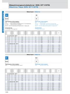
Transcription of Taps for internal treads - basic technical data
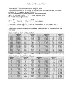
1 1)- Taps for internal threads basic technical data Taps terminology With reference of the figure N 1 the general part of a tap are: Fig. N 2-(Vergnano- Chieri Torino) Chamfer: the taper on the threads at the front end of the tap made by grinding and relieving the crests of the first few teeth. d1 = Nominal diameter. The diameter used for the purpose of general identification dm = Pitch diameter. The diameter measured where the width of the thread is equal to half the pitch d2 = Shank diameter. The diameter of the shank d3 = Chamfer diameter. The diameter at the leading end of the chamfer. d4 = Neck diameter. The diameter of the reduced section between the thread and shank of the tap d5 = Core diameter. The diameter of the circle tangent to the bottom of the flutes. L1 = Total length. The complete length of the tap from end to end, excluding external centers L2 = Thread length. The length of the theaded section of the tap.
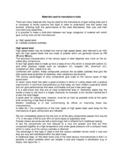
2 L3= Usable length. The length measured from the front end of the tap to the end of the neck section. This length determines the maximum threadable depth on taps with reinforced shank L4 = Chamfer length. The length of the chamfer measured parallel to the tap axis, excluding the chamfer bevel. L5 = Flute length. The axial length of the flute including the cutter sweep. Square a : The square with rounded corners formed b four flats parallel to the tap axis. The square serves to drive the tap. Cm = External center Cf = internal center. About the terminology of the threads the reference is the figure N 2 Figura N 3- (Vergnano Chieri Torino) P = Pitch. Distance measured parallel to the tap axis, between two corresponding and successive points on the thread profile. = Angle of thread. The angle between the flanks of the thread (measured in an axial plan) = Thread lead angle. Angle made by the spiral of the thread and a plane perpendicular to the tap axis, measured on the pitch diameter line.
3 = Chamfer angle. Angle between the chamfer and the tap axis, measured in an axis plane. = Rake angle. Angle between the cutting face of the tap and a radial line passing though the crest of the tooth at the cutting edge. T = Land width is the chordal width of material between two successive flutes. Flute: the longitudinal channels in a tap which create cutting edges. The flutes provide space for chips and passage for coolant/lubricant. = Spiral flute angle. Angle formed by the flutes and the tap axis. = Pitch diameter relief. The radial reduction of the pitch and/or major diameter behind the cutting edge of the tap. The relief confer cutting properties and provides clearance between the part being threaded and the tap threads. = Chamfer relief. Radial reduction of the major diameter on the tap chamfer behind the cutting edge. The chamfer relief confers cutting properties to the tap. In the metric system the nominal diameter and the pitch are expressed in millimeter, whereas in the Whitworth system the diameter are expressed in inch and the pitch are indicated in threads per inch.
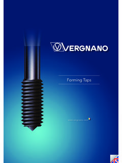
4 Tap tolerances and recommended application ranges Standard fit for a thread correspond to tolerance class ISO 2/6H. For more precise fits, without allowance on thread flank, tolerance class ISO 1/4H must be chosen. ISO 3/6G is used in case of loose fits, with large allowance, which is often required for subsequent coatings. Between classes 6H and 6G, as well as between classes 6G and 7G, tap manufactures produce taps with tolerance 6HX and 6GX. These taps are used for tapping abrasive materials, such as cast iron or Al-Si alloy, in order to increase their tool life. Another important application is on forming taps, which create the thread by plastic deformation and not by cutting. In this case, due to the elastic return of the material, in order to obtain a thread 6H tolerance, a 6HX tap must be used. The tolerances described are collected in the European standard EN 22857. For American tolerances, according to ASME B1.
5 ! (classes 3B, 2B, 2BX), the position in the figure N 4 are only indicative, since they are function of tap diameter. We thank the company Vergnano (Chieri Torino - Italy) for the data presented in this report. ISO Tap Tolerance DIN Tap tolerance ASME/ANSI Tap tolerance Tolerance class, internal thread (nut) Application ISO 1 4H 3B 4H 5H Fit without allowance ISO 2 6H 2B 4G 5G 6H Normal fit ISO 3 6G 1B 6G 7H 8H Fit with allowance 7G 7G 8G Loose fit, for subsequent coating 3- Tolerance comparison between nut thread and tap (Vergnano Chieri- Torino) Fig. N 4 Tolerance range comparison