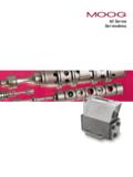
Transcription of Brush Torque Motors - Moog Inc.
1 Moog Components Group MotorsBrush Torque Motors TYPICAL applications Speed and rotation control systems Gimbals for FLIR and inertial navigation systems Stabilized gun and fire control systems for combat vehicles Fire control radars for land and ship board defense Cockpit instrumentation for military and commercial aircraft Missle seeker and fin actuator systems Space and vacuum instruments, actuation systems and momentum wheelsFEATURES Double insulated high temp magnet wire minimizes leakage current, promotes superior insulation Molded Brush block assembly features interchangeable Brush blocks, optimizing Brush position on commutator.
2 Brush contour is done on automatic tooling rather than run-in individually. Brushes mechanically fastened to Brush spring in addition to soldering assures Brush alignment during soldering operation plus proper mechanical and electrical bond between Brush spring and Brush . Stable high temp encapsulation material minimizes movement or working of windings under large temperature variations. This high temp material will not crack under temperature variations, and eliminates voids, exposed windings and humidity traps.
3 Special magnetic material alloy allows higher Torque per unit of volume, higher Torque to inertia ratio. Plated magnet assemblies resist environmental extremes and require no special handling Rare earth magnets typical High Torque and low speed High Torque to inertia ratio Low speed with high accuracy Compact Large axial holes through armature for easy application to shafts and bossesMoog Components Group designs and manufactures precision motion technology components and subsystems for defense.
4 Aerospace and industrial specialty DC Brush Torque and servomotors can be supplied housed with a variety of shaft configurations but typically as a direct drive rotor / stator part-set that will be directly attached to the load. This form of attachment eliminates backlash and increases servo stiffness for an optimized direct drive Torque Motors are used in applications that require high Torque at slow speeds with input power minimized. Our DC servomotors are used in applications that require high speed and positional accuracy.
5 Custom controllers can be supplied on a design-to- specification more information about how this product can be tailored to fit your specific application, contact our applications : This catalog contains basic marketing information and general part descriptions of Moog Components Group product lines. With respect to the export regulations, the products described herein are controlled by the Commerce Department or the State Department. Contact Moog Components Group for additional detail on the export controls that are applicable to your Components Group RotorBrushless MotorsOutside RotorBrushless MotorsDirect Drive Brushless MotorsBrush MotorsPosition SensorsSynchrosDrive ElectronicsGearmotors and EncodersIntegrated MechanismsApplication InformationBrush MotorsDesign ConsiderationsAll diameters listed have finished, ground lamination surfaces.
6 They can be complemented with rings and hubs for mounting Components Group Torque Motors are normally delivered in kit form. If you require integral bearings such as, a cartridge assembly containing a torquer motor and synchro, potentiometer or similar component, we can design the entire assembly to your mechanical dimensions and performance ConsiderationsSince Torque Motors are normally delivered in kit form, you provide the mounting surfaces and bearings. When you design the mechanics of the mount, be sure to observe these rules:1.
7 Eccentricities from the inner member mounting surface should not exceed inches for Alnico designs and inches for rare earth motor Surfaces in contact with the permanent magnet portion of the motor must be The bore of the mounting surface should be perpendicular to the mounting seat within inch for Alnico designs and inches for rare earth ConsiderationsFor each mechanical configuration shown, different winding designs to modify Torque , Torque sensitivity, DC resistance, and so on, can be supplied by Moog Components Group FROM TO MULTIPLY BY Conversion TableLength inches cm feet cm cm inches.
8 3937 cm feet x 10-2 Mass oz g lb g g oz x 10-2 lb oz g lb x 10-3 oz lb x 10-2 Torque oz-in g-cm lb-ft g-cm x 104 g-cm oz-in x 10-2 lb-ft oz-in g-cm lb-ft x 10-5 oz-in lb-ft x 10-3 Rotation rpm degrees/s rad/s degrees/s degrees/s rpm .1667 rad/s rpm degrees/s rad/s x 10-2 rpm rad/s .1047 Moment Of Inertia oz-in2 g-cm2 lb-ft2 g-cm2 x 105 g-cm2 oz-in2 x 10-3 lb-ft2 oz-in2 x 103 g-cm2 lb-ft2 x 10-6 oz-in2 lb-ft2 x 10-4 oz-in-sec2 g-cm2 x 104 Electrical Time Constant E ms LM / RMMechanical Time Constant M msPower Input, Stalled At Peak Torque (25 C)
9 PP watts VP IPViscous Damping Coefficients KT KE Zero Source Impedance FO oz-in per rad/s RM Infinite Source Impedance FI oz-in per rad/s Small % of FO1 motor Friction Torque (Actual) TF oz-in TF Maximum Power Rate P oz-in/s2 TP2 / JM Maximum Theoretical Acceleration M rad/s2 TP / JM2 Theoretical No Load Speed NL rad/s VP / KE1 TF is specified as a maximum value and includes Brush friction, magnetic detent and test fixture bearing friction which is considered In cases where motor is to be operated at some voltage less than VP due to power supply limitations the new NL becomes VA / KE where VA = voltage RMKE KT RELATIONSHIP TO PUBLISHEDPARAMETER SYMBOL UNITS PARAMETERT able 1to suit your special system requirement.
10 In each case, you have the option of selecting one of the existing designs or specifying a new winding designed to meet your special requirements. If your power source (voltage or current) is limited, the mathematical relationships shown in Table 1 will allow you to calculate a particular performance characteristic at the voltage or power capability of your existing power following frame sizes represent only a small sampling of the total range manufactured. Consult factory for additional designs.