Transcription of Bulk Metal Foil Technology Hermetically Sealed …
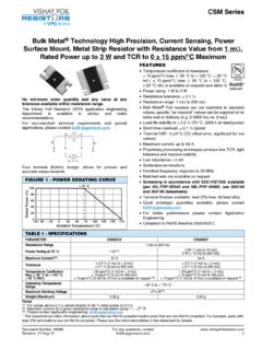
1 bulk Metal foil TechnologyHermetically Sealed Power and Current Sensing Resistor withTCR of 2 ppm/ C and Power up to 10 WattsVHP-3, VHP-4, VPR247 Vishay foil Resistors Document Number: 63005 For any questions, contact: 23-Mar-101 Any value available within resistance rangeVishay bulk Metal foil power resistors offer the bestapproach to low value power and current sensing when acombination of accuracy, tight TCR, low thermal EMF, lowvoltage coefficient, Kelvin connection, and long term stability(under power) are Models VHP-3 and VHP-4 offer all weldedconstruction and screw mounting directly to a Metal heat sinkfor maximum heat transfer.
2 Hermetic sealing and nitrogenback fill provide the maximum protection againstenvironmental stresses, thereby ensuring long term special feature of this construction is Kovar eyelet s andOFHC solder plated copper leads providing the lowestthermal EMFs in the Model VPR247 has many of the advantages of theVHP-4 but with significantly reduced size and weight. It alsohas gold plated copper Application Engineering department is available toadvise and to make recommendations. For non-standardtechnical requirements and special applications, pleasecontact Temperature coefficient of resistance TCR: 2 ppm/ C typical (- 55 C to + 125 C,+ 25 C ref.)
3 (see tables 1 and 2) Tolerance: to % (see tables 1 and 2) Power rating (heat-sinked): 10 W Load life stability: % at 25 C, 2000 h at rated power Resistance range: to 80 k Electrostatic discharge (ESD) above 25 000 V Non inductive, non capacitive design Rise time: ns without ringing Current noise: < - 40 dB Thermal EMF: V/ C typical Voltage coefficient: < ppm/V Non inductive: H Non hot spot design Terminal finishes available:VHP-3 and VHP-4:lead (Pb)-freetin/lead alloyVPR247:gold plated Any value available within resistance range ( 1K234) Prototype samples available from 48 h.
4 For moreinformation, please contact For better performances, please contact ApplicationEngineeringNotes1. Weight of VHP-3 and VHP-4 = 15 g maximumVPR247 = 7 g maximum2. Available up to 500 3. - 55 C to + 125 C, + 25 C See figure 5* Pb containing terminations are not RoHS compliant, exemptions may applyAvailablePb-freeRoHS*COMPLIANTTABLE 1 - VHP-31) SPECIFICATIONSRESISTANCE RANGE ( )TIGHTEST TOLERANCETYPICALTCR3), 4)MAXIMUMTCR3)50 to 80K % 2 ppm/ C 5 ppm/ C25 to < 50 % 7 ppm/ C10 to < 25 % 10 ppm/ C5 to < 10 % 13 ppm/ C2 to < 5 % 20 ppm/ C1 to < 2 % 25 ppm/ to < 1 % 50 ppm/ to < % to < %TABLE 2 - VHP-4 AND VPR247 SPECIFICATIONS1), 2)RESISTANCE RANGE ( )TIGHTEST TOLERANCETYPICALTCR3), 4)MAXIMUMTCR3)
5 10 to 500 % 2 ppm/ C 5 ppm/ C5 to < 10 % 6 ppm/ C2 to < 5 % 8 ppm/ C1 to < 2 % 10 ppm/ to < 1 % 15 ppm/ to < % 20 ppm/ to < % 25 ppm/ to < % 30 ppm/ CVHP-3, VHP-4, VPR247 Vishay foil Resistors any questions, contact: Number: 630052 Revision: 23-Mar-10 Kelvin (4-terminal) connections are used for these low ohmic value products to measure a precise voltage drop across theresistive element. In these applications the contact resistance, lead resistance, and their TCR effect may be greater than that ofthe element itself and could cause significant errors if the standard 2-terminal connection is used.
6 Figure 2 shows a highimpedance measurement system where r5 approaches infinity and Im approaches zero resulting in negligible IR drop through r3and r4 which negates their lead resistance and TCR effect. With the voltage sense leads E1 and E2 inside of r1 and r2 theresistance and TCR effect of the current leads, I1 and I2 are negated and only the resistance and TCR of the element R aresensed. This method of measurement is essential for precise current 3 - GENERAL SPECIFICATIONSS tabilityLoad life 2000 h % maximum R, 3 W in still air at + 25 C % maximum R under full rated power(10 W at + 25 C on heat sink)Shelf life % (5 ppm) maximum R/yearPower RatingAt + 25 C (see Fig.)
7 1)10 W or 3 A - heat sink2)3 W or 3 A - free airCurrent Noise< V (RMS)/V of applied voltage(- 40 dB)High Frequency OperationRise ns at 1 k without ringingInductance (L)3) H maximum; H typicalCapacitance (C) pF maximum; pF typicalVoltage Coefficient< ppm/VOperating Temperature Range- 55 C to + 150 CHermeticity10-7 Atmospheric cc/s maximumMaximum Working Voltage7)600 VThermal EMF8) V/ C maximum (lead effect) V/W maximum (power effect)FIGURE 1 - POWER DERATING CURVE+ 100+ 75+ 50+ 250 Ambient Temperature ( C)Percent of Rated Power- 55 CRated Power- 75 - 50 - 25 0 + 25 + 50 + 75 + 100 + 125 + 150 + 175 FIGURE 2 - KELVIN CONNECTIONr1r2I1I2r3r4 RImr5 0 FIGURE 3 - VHP-3, VHP-4 STANDARD IMPRINTING AND DIMENSIONS in inches (millimeters)Case not active.
8 Insulators not required; mounting hardware not dia ( ) ( ) ( ) ( ) ( ) ( ) ( ) ( )TO-3 CapTO-3 ( ) Dia. ( ) ( ) ( ) ( ) ( ) ( )Max. ( ) ( ) ( ) ( ) ( ) ( ) Dia. ( ) ( ) ( ) ( ) ( ) ( ) ( ) ( )VHP-3 VHP-4 (4 terminal)Standard MarkingArrangementE1E2I1I2 Model %B0729 Date CodeBYear07 Week29 ResistanceValueTolerancePrint SpecVHP-3, VHP-4, VPR247 Vishay foil Resistors Document Number: 63005 For any questions, contact: 23-Mar-103 FIGURE 4 - VPR247 STANDARD IMPRINTING AND (Dia.)
9 Thru Hole)CWLLLDate Code10 Week07 YearVISHAYVPR247 XXXX0R2000 1 %HSALST oleranceResistanceValueGold PlatedCopper ExtensionFIGURE 5 - TYPICAL TCR CURVE(For more details, see tables 1 and 2) - 50 - 25 0 + 20 + 50 + 75 + 100 + 125- 55+ 150+ 100+ 50 0- 50- 100- 150- 200 RR(ppm)Ambient Temperature ( C) 2 ppm/ C (+ 25 C Reference)FIGURE 6 - TRIMMING TO VALUES Mutual InductanceReduction dueto Change inCurrent DirectionCurrent PathBefore TrimmingNote: foil shown in black, etched spaces in whiteInterloop CapacitanceReduction in SeriesTrimming ProcessRemoves this Materialfrom Shorting Strip AreaChanging Current Pathand IncreasingResistanceCurrent PathAfter TrimmingVHP-3, VHP-4, VPR247 Vishay foil Resistors any questions, contact: Number: 630054 Revision: 23-Mar-10 Notes1.
10 Whichever is Heat sink chassis dimensions and requirements perMIL-PRF-39009/1:3. Inductance (L) due mainly to the The resolution limit of existing test equipment (within themeasurement capability of the equipment, or essentially zero ).5. Not to exceed power rating of Vishay test data as compared to MIL-PRF-39009 is shown forillustration purposes, Vishay test conditions that deviate from theMil test method are noted within Maximum ambient temperature rating is + 150 Maximum overload rating is 15 W (5 x rated power in free air.)