Transcription of CABLE TRAY SYSTEMS GUIDE
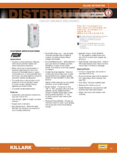
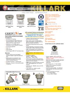
1 CABLE TRAY SYSTEMS GUIDES teel Ladder | Aluminum Ladder | Wire BasketSTEEL LADDERALUMINUM LADDERWIRE BASKET2 HUBBELLH ubbell Wiring Device-Kellems and Hubbell Premise Wiring are divisions of Hubbell Incorporated, a headquartered manufacturer with over 130 years of supplying solutions for the electrical and data markets. Hubbell s strength is demonstrated by a long-standing reputation for supplying reliable electrical and cabling support products. Our highly trained sales force and distribution network have earned global recognition in the structured cabling industry. With offices in many countries and a worldwide distribution network , Hubbell makes customer satisfaction our highest TO HELPW orking with schematics and blueprints can be a very time-consuming and costly part of doing business.
2 Many contractors employ full-time staff to count components when planning jobs and providing estimates. This task can be handled much more efficiently using Hubbell s take off services. Hubbell Take Off Support provides the contractor, engineer, end user a completed BOM, including all related products, counts, symbol legends and information required to price a project. Don t spend the many hours required to do counts and create BOMs for projects, rely on Hubbell s take off services to do it for of BIM models available to assist with data center design: Cabling infrastructure products CABLE management Power Grounding BIM models CAD drawings CSI specification textBIMENVIRONMENTS teel LadderAluminum LadderWire BasketINDOORC ommercialGeneral UseHigh VolumePreGalvanizedData CenterGeneral UseHigh VolumePreGalvanizedIndustrial-All Applications304 Stainless, HD GalvanizedFood Processing--304 StainlessOUTDOORG eneral Rooftop-All ApplicationsHD GalvanizedPipe-All Applications-Corrosive/Ocean-All Applications304 Stainless.
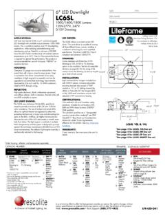
3 HD GalvanizedTray SelectionCable Tray SYSTEMS Guide3 Tray SelectionCABLE TYPES teel LadderAluminum LadderWire BasketPOWERA rmored BX-All ApplicationsAdd Dividers for Power/DataHigh Voltage-All Applications-DATAC ategory CablingAdd Dividers for Power/DataAdd Dividers for Power/DataAdd Dividers for Power/DataFiber Optic--Add InsertsFiber Optic- ArmoredAll ApplicationsAll ApplicationsAll ApplicationsPERFORMANCES teel LadderAluminum LadderWire BasketFINISHM aterialSteelAluminumSteel, StainlessColorBlack, GrayAluminumSteel, Black, Custom PaintLOADINGRung Spacing9 9 4 Max Loading45 lbs/ftUp to 100 lbs/ftUp to 150 lbs/ftSupport Pitch5 12 6 Tray Length6 to 10 12 10 Standards-cULus, NEMA VE1, CSA Ladder SystemStraight SectionsWidth Inches (mm)6 (1829) Length10 (3048) LengthGrayBlackGrayBlack6" (152)12" (305)18" (457)24" (610)HLS0606 GHLS0612 GHLS0618 GHLS0624 GHLS0606 BHLS0612 BHLS0618 BHLS0624 BHLS1006 GHLS1012 GHLS1018 GHLS1024 GHLS1006 BHLS1012 BHLS1018 BHLS1024 BNote.
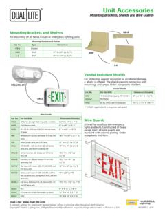
4 Width = outside to outside TurnsWidth Inches (mm)Inside Radius 90 Outside Radius 90 GrayBlackGrayBlack6" (152)12" (305)18" (457)24" (610)HLI0690 GHLI1290 GHLI1890 GHLI2490 GHLI0690 BHLI1290 BHLI1890 BHLI2490 BHLO0690 GHLO1290 GHLO1890 GHLO2490 GHLO0690 BHLO1290 BHLO1890 BHLO2490 BWidth Inches (mm)Flat Turns 90 Corner Support Bracket Internal Radius 90 , " (210) WidthGrayBlackGrayBlack6" (152)12" (305)18" (457)24" (610)HLF0690 GHLF1290 GHLF1890 GHLF2490 GHLF0690 BHLF1290 BHLF1890 BHLF2490 BHLCGHLCBW idthModular System: Easily Configured for New and Existing CABLE to: Floors, Walls, Ceilings, Equipment Racks, and : Secure Ladder to Cabinet Tops Using J-bolt Kit and Drilling Holes as s NEXTFRAME Ladder Tray is the effective and widely used CABLE runway that supports and delivers bundles of CABLE between cabinets, racks, and closets, along walls, and suspended from Ladder Tray features light, rugged, tubular steel construction.
5 It is designed for mechanical support and strain relief in long runs of CABLE and creates a smooth gradual bend for CABLE . Rail and stringer material is 16 ga steel NEXTFRAME Ladder Tray is available in popular gray and black finishes to complement equipment in any data center. The complete NEXTFRAME Ladder Tray system features a broad line of sizes and fittings required for proper Supports horizontal/vertical and overhead CABLE management Durable black or gray powder coat finish Supports UTP or fiber cabling Complete family of accessories includes: wall supports and brackets, CABLE drops, retaining posts, splice kits, and ceiling mounting kitsSPECIFICATIONS Material: 16 ga.
6 Tubular steel Durable powder coat Stringer dimensions: W x H Rung spacing: Weight capacity: 45 in data centers, the equipment room, and telecommunications room to provide racking, CABLE management, and grounding for network KitTypeContentsMaterialCatalog TrayIncludes: (1) 9" #6 conductor with long barrel lugs crimped on both ends, stainless steel hardware, labeled, antioxidantCopperHGRKTD9 DHLSHLFHLCHLOHLI5 Ladder Standoff SupportDescriptionGrayBlack14" vertical supportHLH14 GHLH14BJ-Bolt KitDescriptionCatalog Number2-pack, galvanizedHLJBV ertical Wall BracketDescriptionBlack2 clipsHLVWBKP rotective End CapsDescriptionBlack2-packHLECPK2 Mounting Kit to Relay RackDescriptionBlack3" rackHLMPK196" rackHLMPK19 DFoot KitDescriptionBlack2-pack with splicesHLRFWall/Rack Mounting KitDescriptionBlackIncludes (1) HLMPK19, (1) HLX0612, (1)
7 40"L x 12"W ladder sectionHLWRKC eiling Mounting KitDescriptionBlackCeiling mounting kit with two 6 x threaded rodsHLCMKB rackets onlyHLCFS plice KitsButt Splice KitSwivel Splice KitT-Junction Splice KitHLBSKHLSSKHLTKWall Angle SupportsWidth Inches (mm)GrayBlack6-12" (152-305)HLX0612 GHLX061218" (457)HLX1518 GHLX151824" (610)HLX24 GHLX24 Triangle Wall SupportsWidth Inches (mm)GrayBlack6" (152)HLTSB06 GHLTSB06B12" (305)HLTSB12 GHLTSB12B18" (457)HLTSB18 GHLTSB18B24" (610)HLTSB24 GHLTSB24 BCable Radius DropLadder Width Inches (mm)Actual Width Inches (mm)Black6" (152) " (114)HLCD06*12" (305) " (273)HLCD1218" (457) " (425) " (191)HLCDS*Can also be mounted on stringerElevation KitHeight Inches (mm)Black2 3" (51 76)HLEK234 6" (102 152)HLEK46 CABLE Retaining Fence PostsNominal Height Inches (mm)GrayBlack6" (152)HLP06 GHLP06B8" (203)HLP08 GHLP08B10" (254)HLP10 GHLP10B6 Aluminum Ladder SystemSPAN/LOAD CLASS DESIGNATIONSC ommonly called the Load Class, this defines the load-carrying capability of the tray for a specific support span distance.
8 The design and cost of the CABLE tray is greatly affected by this designation. In order to determine the most appropriate and economical system, a class should be selected that reflects the actual total working load and support span for each STATIC LOADS: Some applications may require the CABLE tray to support the weight of a single, dead object in addition to the CABLE loads. Specifications typically require this to be applied at the midpoint of the span between the tray supports, which is the worst-case incorporate this in the tray design the following formula can be used to convert the concentrated static load in pounds to an equivalent uniform load (W ) in pounds per foot.
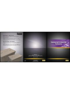
9 That equivalent load can then be combined with the weight of cables, tray contents, and other loads that are also expressed in lbs/ft to determine the total Working x (Concentrated static load, lbs)support span lenth, ft Note: This calculation is based on the load being applied at the center of the tray in the middle of a rung or bottom. If the specification requires the concentrated static load to be applied on top of one side rail, then the equivalent uniform load will be 2 times the result of this : A CABLE tray is to be supported on 20 spans. It shall contain 50 lbs/ft of cables and support 15 lbs/ft of snow load. It is also required to support a 250 pound concentrated static load applied in the center of the tray the calculation above, the concentrated static load is converted to an equivalent uniform load as follows: 2 x 250 lbs / 20 ft = 25 lbs/ftThe Total Working Load will be the combination of all 3 loads, expressed in lbs/ft:Cables40 lbsSnow+ 15 lbs/ftConcentrated Load+25 lbs/ftTotal Working Load: 80lbs/ftRefer to the chart on the right.
10 With a support span of 20 and a total working load of 80 lbs/ft, a NEMA Class 20B tray rated at 75 lbs/ft will not be adequate. A NEMA Class 20C tray, rated at 100 lbs/ft, will be Class Designations Per NEMA Standard VE1/CSA Load LBS/FT (Kg/M)Support Span, Feet (Meters)5 Ft ( M)8 Ft ( M)10 Ft ( M)12 Ft ( M) 16 Ft (4 . 9 M)20 Ft ( M)25 (37)5AA8AA10AA12AA20AA45 (67)D50 (74)5A8A 12A 16A20A 65 (97)C75 (112)8B12B16BE* or 20B100 (149)8C12C16C20C120 (179)D200 (299)E* CSA Classes D and E are applicable to both and meter support spans. The appwropriate support span should also be included when specifying these classes (example: D-3M).