Transcription of Cam Positioner H8PS - Omron
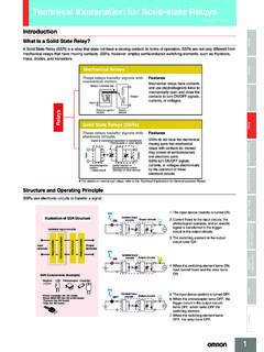
1 CSM_H8PS_DS_E_6_21 Cam PositionerH8 PSThis Compact Cam Positioner , Popular for Its Ease-of-use, Now Comes with Even Better Functions. Compact 8-, 16-, and 32-output Models available that are 1/4-DIN size at 96 x 96 mm. High-speed operation at 1,600 r/min and high-precision settings to ensure widespread application. Highly visible display with backlit negative transmissive LCD. Advance angle compensation function to compensate for output delays. Bank function for multi-product production (8 banks). ( h8ps -16@/-32@ models.) Speed display and pulse output. Approved standards: UL/CSA and to Safety Precautions for All Counters and Safety Precautions on page 18 and with 8, 16, or 32 Outputs The lineup includes Models with 32 outputs in a compact 1/4-DIN size. Using the optional Parallel Input Adapter (Y92C-30) enables expanding to up to 64 outputs for one encoder to support anything from a simple positioning application to a large-scale system.
2 Simple ProgrammingThe programming method is designed based on a one key-one action concept for settings that could not be simpler. Both initial settings and factory adjustments are , Backlit Negative LCDsLarge LCDs, red for the process value and green for set values, show a wealth of operation information, making operating status visible at a Speed Up To 1,600 r/minHigh Precision Up To (at 720 Resolution)High-speed, high-precision applications can be easily handled and productivity Function for Multi-product Production Up to eight different programs can be registered in advance to enable fast and easy switching between products (16/32-output Models only).USB Communications for Easy Setting from a ComputerOptional Support Software can be used to enable programming from a personal computer via USB communications.
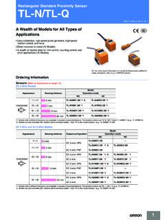
3 Programs can be easily copied, saved, printed, and much Display and Speed Alarm OutputBoth the speed (rotations/minutes) and present angular position can be displayed at the same time. Alarm outputs can be produced for both upper and lower speed limits. Advance Angle Compensation Function to Compensate for Output DelaysThe advance angle compensation (ADV) function automatically advances the ON/OFF angle of outputs in proportion to machine (encoder) speed to compensate for the delay in timing of ON/OFF operation. ADV values can be set individually for 7 cam Output for Timing ControlThe number of pulses per rotation and the pulse output start angle can be set to enable operations like adjusting timing with a PLC or outputting to a rotation Models16-output Models 32-output Models96 mm96 mmCAMSTEP127 RUNCAMSTEP127 RUNS witchablePresent angular positionSpeedSpeedPresent angular positionSpeedUpper limit alarm outputLower limit alarm outputUpper limitLower limitErrorsCam program settings100 8 compensation180 92 172 At high-speed (400 r/min)Pulse outputPLCR otation meterH8PS2 Model Number Structure Model Number LegendOrdering Information List of ModelsCam Positioner Dedicated Absolute Encoder Accessories (Order Separately)Note.
4 Ask your Omron representative about the availability of non-standard USB CablesNote:If you can t purchase recommended replacement, please purchase commercially available USB cable that attached ferrite @@@ Number of outputs8:8 outputs 16: 16 outputs 32: 32 outputs 2. Panel language B: English 3. Mounting method None: Flush mountingF:Surface mounting/track mounting4. Output configuration None: NPN transistor output P:PNP transistor output Number of outputs Mounting method Output configuration Bank function Model 8 outputs Flush mountingNPN transistor output NoH8PS-8 BPNP transistor output h8ps -8 BPSurface mounting/track mountingNPN transistor output h8ps -8 BFPNP transistor output h8ps -8 BFP16 outputsFlush mountingNPN transistor output YesH8PS-16 BPNP transistor output h8ps -16 BPSurface mounting/track mountingNPN transistor output h8ps -16 BFPNP transistor output h8ps -16 BFP32 outputsFlush mountingNPN transistor output h8ps -32 BPNP transistor output h8ps -32 BPSurface mounting/track mountingNPN transistor output h8ps -32 BFPNP transistor output h8ps -32 BFPType Resolution Cable length Model Economy2562
5 ME6CP-AG5C-C 256P/R 2 MStandard2561 mE6C3-AG5C-C 256P/R 1M2 mE6C3-AG5C-C 256P/R 2M360E6C3-AG5C-C 360P/R 2M720E6C3-AG5C-C 720P/R 2 MRigid2562 mE6F-AG5C-C 256P/R 2M360E6F-AG5C-C 360P/R 2M720E6F-AG5C-C 720P/R 2 MNameSpecificationModel Discrete Wire Output Cable2 mY92S-41-200 Connector-type Output Cable2 mE5ZE-CBL200 Support SoftwareCD-ROMH8PS-SOFT-V1 Shaft Coupling for the E6CP Axis: 6 mm Coupling for the E6C3 Axis: 8 mm Coupling for the E6F Axis: 10 mm Cable (See note.) 5 m (same for E6CP, E6C3, and E6F)E69-DF5 Parallel Input AdapterTwo Units can operate in parallel. Y92C-30 Protective Cover---Y92A-96 BWatertight Cover---Y92A-96 NTrack Mounting Base---Y92F-91 Mounting Track50 cm mm (l t)PFP-50N1 m mm (l t)PFP-100N1 m 16 mm (l t)PFP-100N2 End Plate---PFP-MSpacer---PFP-SNameRecommend ed manufacturerSpecificationModel USB CableELECOM , 2mU2C-MF20 BKH8PS3 Specifications RatingsItemH8PS-@BH8PS-@BFH8PS-@BPH8PS-@ BFPR ated supply voltage24 VDCO perating voltage range85% to 110% of rated supply voltageMounting methodFlush mountingSurface mounting, track mountingFlush mountingSurface mounting, track mountingPower consumptionApprox.
6 W at VDC for 8-output modelsApprox. W at VDC for 16-/32-output modelsInputsEncoder inputConnections to a dedicated absolute encoder External inputsInput signals 8-output Models: None16-/32-output Models: Bank inputs 1/2/4, origin input, start input Input typeNo voltage inputs: ON impedance:1 k max. (Leakage current: approx. 2 mA at 0 )ON residual voltage: 2 V max., OFF impedance: 100 k min., Applied voltage: 30 VDC input signal width: 20 msOutputs Cam outputsRUN output NPN open-collector transistor outputs 30 VDC max., 100 mA max. (Do not exceed A total for all cam outputs and the RUN output.), residual voltage: 2 VDC open-collector transistor outputs30 VDC max. ( VDC for 16-/32-output Models), 100 mA max. (Do not exceed A total for all cam outputs and the RUN output.), residual voltage: 2 VDC outputNPN open-collector transistor output 30 VDC max.
7 , 30 mA max., residual voltage: VDC open-collector transistor output 30 VDC max. ( VDC for 16-/32-output Models)30 mA max., residual voltage: 2 VDC of outputs 8-output Models: 8 cam outputs, 1 RUN output, 1 pulse output 16-output Models: 16 cam outputs, 1 RUN output, 1 pulse output 32-output Models: 32 cam outputs, 1 RUN output, 1 pulse output Number of banks8 banks (for 16-/32-output Models only)Display method7-segment, negative transmissive LCD (Main Display: 11 mm (red), Sub-display: mm (green))Memory backup methodEEPROM (overwrites: 100000 times min.) that can store data for 10 years operating temperature 10 to 55 C (with no icing or condensation)Storage temperature 25 to 65 C (with no icing or condensation)Ambient humidity25% to 85%Degree of protection Panel surface: IP40, Rear case: IP20 Case color Light gray (Munsell 5Y7/1)H8PS4 CharacteristicsNote: output precision, however, is 2 max.
8 For Encoder with 256 resolution (P/R). 32-output Models can have 10 steps set for any one output, there must be no more than 160 steps total set for all cam maximum is 1000 r/min when an E6CP-AG5C-C Encoder is connected. stands for Advance Angle unit increments at a resolution of 720, 1 increments at a resolution of 256 or 360 (See note 1.)Number of stepsUp to 10 steps can be set for each cam to turn the output ON/OFF 10 times. (See note 2.)Inputs Encoder input Connections to a dedicated absolute encoder Response rotation speed (in Run/Test Mode)1600 r/min max. at a resolution of 256 or 360 (1200 r/min max. if ADV function is set for 4 or more cams) (See notes 3 and 4.)800 r/min max. at a resolution of 720 (600 r/min max. if ADV function is set for 4 or more cams) Includes error data detectionEncoder cable extension distance 256/360 resolution100 m max.
9 At 330 r/min or less52 m max. at 331 to 1200 r/min (331 to 900 r/min if ADV function is set for 4 or more cams)12 m max. at 1201 to 1600 r/min (901 to 1200 r/min if ADV function is set for 4 or more cams)720 resolution100 m max. at 330 r/min or less52 m max. at 331 to 600 r/min (331 to 450 r/min if ADV function is set for 4 or more cams)12 m max. at 601 to 800 r/min (451 to 600 r/min if ADV function is set for 4 or more cams)Output response time ms max. Insulation resistance100 M min. (at 500 VDC) between current-carrying terminals and exposed non-current-carrying metal parts, between all current-carrying parts and the USB connector Dielectric strength 1000 VAC, 50/60 Hz for 1 min between current-carrying terminals and exposed non-current-carrying metal parts500 VAC, 50/60 Hz for 1 min between current-carrying section and USB connector, and between current-carrying terminals and non-current-carrying metal part of output connectorImpulse withstand voltage 1 kV between power kV between current-carrying terminals and exposed non-current-carrying metal parts Noise immunity 480 V between power terminals, 600 V between input terminals Square-wave noise by noise simulator (pulse width.)
10 100 ns/1 s, 1-ns rise)Static immunity 8 kV (malfunction), 15 kV (destruction)Vibration resistance Destruction 10 to 55 Hz with single amplitude each in 3 directions for 2 hours eachMalfunction10 to 55 Hz with single amplitude each in 3 directions for 10 minutes eachShock resistance Destruction 300 m/s2 3 times each in 6 directionsMalfunction200 m/s2 3 times each in 6 directionsApproved safety standards cULus (Listing): UL508/CSA No. 14 EMC(EMI)EN61326 Emission Enclosure: EN55011 Group1 Class A(EMS)EN61326 Immunity ESD: EN61000-4-2: 4 kV contact discharge 8 kV air discharge Immunity RF-interference: EN61000-4-3: 10 V/m (Amplitude-modulated, 80 MHz to 1 GHz) 10 V/m (Pulse-modulated, 900 MHz 5 MHz) Immunity Conducted Disturbance EN61000-4-6: 10 V ( to 80 MHz)Immunity Burst: EN61000-4-4: 2 kV for power-line1 kV for I/O signal-lineImmunity Surge: EN61000-4-5: 1 kV line to line (power line)2 kV line to ground (power line)Weight Approx.