Transcription of Cannulated Screw System - Stryker MedEd
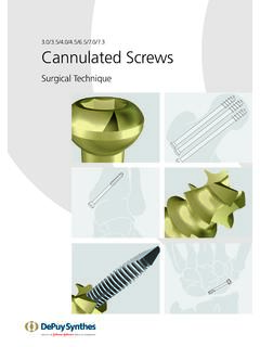
1 Operative Technique IIIC annulatedScrew SystemShoulderElbowHand & WristHipPelvisFemurTibia & FibulaFoot & Ankle2 Asnis III Cannulated Screws This publication sets forth detailed recommended procedures for using Stryker Osteosynthesis devices and offers guidance that you should heed, but, as with any such technical guide, each surgeon must consider the particular needs of each patient and make appropriate adjustments when and as required. A workshop training is recommended prior to first non-sterile devices must be cleaned and sterilized before use.
2 Follow the instructions provided in our reprocessing guide (L24002000). Multi-component instruments must be disassembled for cleaning. Please refer to the corresponding assembly/ disassembly package insert (V15011 & V15013) for a complete list of potential adverse effects, contraindications, warnings and precautions. The surgeon must discuss all relevant risks, including the finite lifetime of the device, with the patient, when : Fixation Screws: Stryker Osteosynthesis bone screws are not approved or intended for Screw attachment or fixation to the posterior elements (pedicles) of the cervical, thoracic or lumbar Page1.
3 Features & Benefits 4 2. System Features 5 Large Diameter Guide Wires 5 Modular Case Design and Elastosil Handles 53. Indications, Precautions & Contraindications 6 Indications 6 Precautions 6 Contraindications 64. Operative Technique - 7 Fractures of the tarsals and metatarsals 75. Operative Technique - 9 Medial and lateral malleolar and pilon fractures 96. Operative Technique - & 11 Intracapsular fractures of the femoral neck Ordering Information - Instruments 15 Screws 16 Instruments 17 Screws 18 & Instruments 19 Screws 21 Screws 23 Additional Information 25 Content 4 Material ChoiceTitanium Alloy (TAV) Stainless Steel (316 LVM)
4 Thread ChoiceImplants available with both partial and fully threaded optionsSelf-Drilling/Tapping DesignEfficient cutting tip design to improve operating efficiencyLarge Diameter Guide WiresTo allow for precise Screw placementthreaded tip engages bone forbetter bone purchase Low Profile Screw HeadHexagonal Driving RecessReverse Cutting FluteTo facilitate removalPackaging Implants individually sterile packaged** , , , partially threaded screws available non-sterile and sterile; lengths 125mm-180mm available non sterile for use in sterilization, case part # and Core Diameter Equal For added strength Features & BenefitsThe Asnis III Cannulated Screw Systems incorporate several features intended to enhance Screw placement, insertion, and removal as follows:5 System FeaturesLarge Diameter Guide WiresThe Asnis III Systems feature larger diameter Guide Wires with tapered core.
5 This design reduces potential for a stress riser at the thread / shank junction. The larger diameter provides greater bending stiffness, to reduce deflection1. This should provide precise Screw Case Design and Elastosil HandlesThe modular case design offers improved aesthetics and better access to the instrumentation, thus simplifying the procedure further. The inclusion of Elastosil allows for better surgeon grip as well as minimizing heat retention following sterilization.* 2mm increments ** 5mm increments ** Steel only1. Bending Stiffness K = (E*PI*d^4)/64.
6 Screw Range Titanium and Steel Partial 1/3 Thread 1/3 Thread 20mm Thread 40mm Thread 25mm Thread 14mm - 50mm* 20mm - 50mm* 40mm - 120mm** 40mm - 130mm** 40mm - 130mm** 55mm - 70mm** 55mm - 80mm** 135mm -180mm** Full 10mm - 50mm* 20mm - 50mm* 30mm - 150mm** 40mm - 150mm** 55mm - 70mm**6 ContraindicationsThe physician s education, training and professional judgment must be relied upon to choose the most appropriate device and treatment option. Conditions presenting an increased risk of failure include: Any active or suspected latent infection or marked local inflammation in or about the affected area Compromised vascularity that would inhibit adequate blood supply to the operative site Bone stock compromised by disease, infection or prior implantation that cannot provide adequate support and/or fixation of the devices Material sensitivity documented or suspected Obesity.
7 An overweight or obese patient can produce loads on the implant which can lead to failure of the fixation of the device or to failure of the device itself Patients having inadequate tissue coverage over the operative site Implant utilization that would interfere with anatomical structures or physiological performance Any mental or neuromuscular disorder which could create an unacceptable risk of fixation failure or complications in post-operative care Other medical or surgical conditions which would preclude the potential benefit of surgerySurgeons should warn patients about these contraindications and limitations when appropriateNote: Contact of an Asnis III Screw with dense bone in a tangential direction may cause a deviation of the Screw and/or a bending of the K-Wire, which may result in damage to the package insert for warnings, precautions, adverse effects and other essential product , Precautions & ContraindicationsIndicationsThe Asnis III Cannulated Screw System is intended for fracture fixation of small and long bones and of the pelvis.
8 The System is not intended for spinal Osteosynthesis systems have not been evaluated for safety and compatibility in MR environment and have not been tested for heating or migration in the MR environment, unless specified otherwise in the product Technique Fractures of the tarsals and metatarsals Fractures of the olecranon, distal humerus Fractures of the radius and ulna Patella fractures Distal tibia and pilon fractures Fractures of the fibula, medial malleolus, or calcaneus Tarso-metatarsal and metatarso- phalangeal arthrodesis Metatarsal and phalangeal osteotomies Osteochondritis dissecans Ligament fixation Fractures of the pelvic ring Other small fragment, cancellous bone fracturesStep One Insert Guide WireUsing the x double Drill Guide, insert a x 150mm guide wire to the appropriate image intensification to control reduction and Guide Wire placement.
9 Place additional Guide Wires as necessary. Remove the double Drill : In dense bone, puncturing the cortex with the x 150mm drill bit to initiate the wire may reduce heat build-up and/or deflection of the wire. Alternative: Substitute the x 150mm Guide Wire with a x 150mm drill bit. Throughout the procedure it is possible to interchange the guide wire and drill : Guide Wires are single use disposables. Do not reuse Guide : A parallel Drill Guide is available for parallel placement of Guide or Washer?Where soft tissue coverage is minimal, use of the countersink to further recess the low profile Screw head may be beneficial.
10 Washers can be applied to spread the load of the Screw head over a greater : The countersink design does not require of the tarsals and metatarsals8 Step 2 Measure for Screw LengthSlide the direct measuring gauge over the x 150mm Guide Wire. The direct measuring gauge measures direct to the tip of the Guide Wire. This allows the final Screw position to correspond with the initial tip position of the Guide appropriate Screw length. Length adjustment is particularly important if the tip is near an articular : Care should be taken to ensure the direct measuring gauge tip engages the bone when a reading is 3 Insert ScrewUsing the Cannulated screwdriver with Elastosil handle and the Screw holding sleeve, insert the selected Screw over the Guide Wire.