Transcription of Centrifugal Compressor Case Study Rev02 - Beta …
1 GMC 2010: Beta Machinery Analysis. Centrifugal Compressor case Study Page 1 Centrifugal Compressor case Study by: Bill Eckert, , , Principal Engineer Beta Machinery Analysis Calgary, AB Canada Gas Machinery Conference October 4-6, 2010 Phoenix, AZ Key words: vibration, pulsation, flow induced vibration, Centrifugal compressors, vortex shedding, blade pass frequency Abstract In 2008, three Centrifugal compressors at a pipeline station were retrofitted with higher head impellers. For the next two years the owner experienced continual vibration problems that caused failures with RTDs, transmitter and position switches. Most of the failures were on the discharge side, but failures did occur on the suction side as well. The cause of the failures was assumed to be flow induced pulsations (also referred to as vortex shedding). Many attempts were made to modify the thermowells and RTDs, but they were not successful in reducing the failures. In early 2010, Beta Machinery Analysis traveled to the site and conducted a vibration and pulsation analysis.
2 After assessing the situation, it was determined that shell mode piping vibration excited by blade pass pulsation was responsible for the problems and not flow induced pulsations as original assumed. This case Study outlines the factors that contributed to the vibration problem and recommended solutions; it predicts interferences between the Compressor and shell mode piping natural frequencies and potential excitation sources such as flow induced or, and, blade passing pulsations; and it also highlights why a Centrifugal vibration Study may be good practice during the initial design (or retrofit) as it is much easier and less costly to make adjustments at the design stage compared to searching for, and solving, the problem in the field. 2010: Beta Machinery Analysis. Centrifugal Compressor case Study Page 2 Centrifugal Compressor case Study Introduction Centrifugal Compressor installations are subject to various forces. Because of the geometry and speeds, the excitation frequencies are often very high.
3 Some of the forces that can act on the Compressor and associated piping are as follows: 1) Mechanical forces due to imbalance of the rotor, or rotor whip or whirl. These are normally well controlled and if excessive are dealt with quickly due to the probability of damaging the Compressor . 2) Flow-induced turbulence can occur at flow past objects intruding into the flow path or discontinuities in the flow path. This may result in high levels of broad band energy that excite acoustic and, or mechanical natural frequencies in the system. 3) Rotating stall forces can be generated by Centrifugal compressors. This typically happens because of flow instabilities in the Compressor at low flows resulting in excitation at frequencies sub-synchronous to the Compressor run speed. 4) Momentum changes due to rapid opening and closing of valves, for instance, create transient pressure waves that are often called water hammer . The pressure rise can be large resulting in significant forces on the piping.
4 5) Pulsations from the Compressor impeller itself can excite acoustic and mechanical natural frequencies of the system. The frequency of excitation is determined by number of blades in the impeller and, or the diffuser, and shaft speed. The strength of the pulsation is determined by the internal geometry and operating point. Generally operating the Compressor off its best efficiency point will increase the source strength of pulsations. In the past most of these factors were not examined at the design stage. More recently industry has recognized the issues that can occur and has begun to specify design studies to minimize the probability of issues. However, some of these phenomena are difficult to predict at the design stage due. This paper will present a case Study of vibration issues at a Centrifugal Compressor station which examines some of these forces. 2010: Beta Machinery Analysis. Centrifugal Compressor case Study Page 3 case Study History There are three single stage Centrifugal compressors at a pipeline station.
5 The units are driven by gas generators at speeds of between 3600 and 5000 rpm. Suction pressure is approximately 615 psig with discharge approximately 830 psig. All three compressors were revamped in 2008. The update consisted of installing a new Compressor wheel with higher head (lower flow) in each unit and replacing the drivers with higher power gas generators. Significant changes were made to the yard piping. However, the piping immediately adjacent to the compressors in the Compressor buildings was not modified. After the Compressor revamp there have been numerous failures of temperature instrumentation and valve position switches. Most of the failures have been on the discharge side of Units A1 and A2. But failures have occurred on the B unit (with a larger Compressor case ) and on the suction side RTD s as well. There have also been failures of position switches on valves downstream of the compressors (within the Compressor buildings). There are no known issues on the yard piping outside the Compressor buildings.
6 Several modifications have been made in an attempt to reduce the number of failures: - shorter thermowells (75mm insertion length vs 150 mm). - oil filled thermowells - RTDs with higher acceleration tolerance - relocating the thermowells from the Compressor casing to the piping Noise was also a concern in the Compressor buildings after the revamp. The primary frequency was found to be at diffuser pass frequency (19X run speed). The suction and discharge piping inside the buildings was insulated to reduce noise levels. Beta Machinery was tasked to look at the vibrations and make recommendations to reduce failures. Investigation One of the likely causes for failure was the thermowell configuration resulting in flow induced turbulence. The flow past the thermowell causes vortices to be shed at a characteristic Strouhal frequency. If that vortex shedding frequency matches the mechanical natural frequency of the thermowell, then a resonance occurs. Resonance results in high vibration that can lead to fatigue failures.
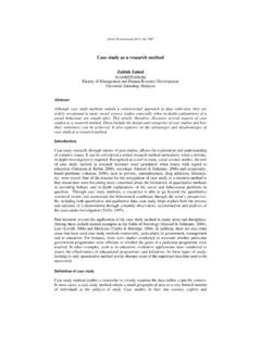
7 However, two different thermowell geometries were installed and it was reported to make no difference to the vibration. The Strouhal (vortex shedding) frequencies were calculated for both thermowell geometries at suction and discharge conditions. Those were compared to the estimated mechanical natural frequencies (1st cantilever mode) of the thermowells. Table 1 shows the comparison. The mechanical natural frequencies were well separated from the vortex shedding frequencies meeting ASME PTC So, there was no apparent link between the flow-induced turbulence and the vibration problem. 2010: Beta Machinery Analysis. Centrifugal Compressor case Study Page 4 Table 1. Mechanical Natural Frequencies and Vortex Shedding Frequencies of Thermowells Figure 1. Unit A2 with initial test points marked. Subsequently, testing of one Centrifugal Compressor (A2) was done on January 12, 2010 with the primary objective to look for pulsation induced issues. Onsite discussions with plant personnel revealed that a loud noise and vibration of the piping developed at higher operating speeds again supporting the likelihood of pulsation.
8 Figure 1 shows the unit tested with suction on the right hand side of the photo and discharge on the left. Initially, peak hold pulsations were measured at the Compressor discharge and Compressor suction eye (marked as points P1 and P2 respectively on the photo) over a speed range of 3600 4500 rpm. As the speed increased, the pulsation in the discharge line increased and spiked at the upper end of the speed range (see Figure 2). The peak pulsation was 24 psi pk-pk (compared to a discharge pressure of approximately 825 psig). There is no guideline, but that pulsation is approximately 3% of the mean pressure. In comparison, the pulsation in the suction eye was considerably lower throughout the tested speed range (less than of mean pressure) and did not develop a significant single peak (see Figure 3). The frequency of the peak pulsation in the discharge was 1274 Hz which was 17X the run speed and equaled the number of vanes in the impeller (blade pass frequency or BPF).
9 The noise in the building changed when the spike in the pulsation Original 150 mm ThermowellNew 75 mm Thermowell Mechanical Natural Freq. (1st Bending Mode of a Cantilevered Beam) 715 Hz 2840 Hz Vortex Shedding Freq. at Suction Conditions (54 F, 615 psig, and 2500 mmSCFD) 370 Hz Vortex Shedding Freq at Discharge Conditions (100 F, 826 psig, and 2500 mmSCFD) 310 Hz V2V1 P1 P2 2010: Beta Machinery Analysis. Centrifugal Compressor case Study Page 5 occurred to what sounded like a single tone, but no sound pressure measurements were conducted at the time. Figure 2. Pulsations in the discharge piping (P1) over 3600 4550 rpm. Suction Pulsation012345050010001500200025003000 Frequency (Hz)Pulsation (psi 0-pk) Figure 3. Pulsations in the Compressor suction eye (P2) over 3600 4550 rpm. Peak hold vibrations were then measured on the discharge and suction piping beside the temperature instrumentation immediately adjacent to the Compressor (marked as points V1 and V2 respectively on the photo) over a speed range of 4100 4510 rpm (Figures 4 and 5).
10 As with the pulsations the vibration on the discharge side was significantly higher than the suction side. The discharge piping is 36 OD with wall thickness. The peak vibration on the discharge was in/s pk at 1284 Hz. Again that frequency was equal to blade pass at 4510 rpm. The vibration is equivalent to 38 g s peak in acceleration terms. Instrumentation that is rated for vibratory service often has an acceleration limit of 10 g s peak. No wonder the RTD s have been failing! Discharge Pulsation051015050010001500200025003000 Frequency (Hz)Pulsation (psi 0-pk)24 psi pk-pk at 1274 Hz 2010: Beta Machinery Analysis. Centrifugal Compressor case Study Page 6 Figure 4. Vibration on the discharge piping beside the thermowell (V1) over 4150 4510 rpm. Suction (Hz)Vibration (in/s 0-pk) Figure 5. Vibration on the suction piping beside the thermowell (V2) over 4150 4510 rpm. The next step was to conduct an operating deflection shape (ODS) analysis on the piping.