Transcription of Optimized Skid Design for Compressor Packages - Beta …
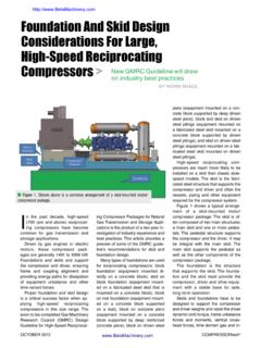
1 Page 1 Optimized Skid Design for Compressor Packages By Chris Harper, Principal Engineer Hongfa Wu, , Senior Engineer Beta Machinery Analysis Presented at: Gas Machinery Conference 2013 October 7 - 10, 2013 Albuquerque, NM Abstract The majority of Compressor Packages are now mounted on steel skids or baseplates. Designing a skid for a new machinery package can be challenging because of these factors: The skids must be designed to avoid resonance and vibration (from dynamic machinery forces and couples). The industry is looking for lower cost Packages . This can drive suppliers to reduce the skid cost and associated stiffness, but an inappropriately designed skid will create vibration and reliability problems.
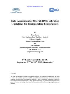
2 In some cases, skids are considered too flimsy for the required application. New designs must consider loading, lifting and transportation issues, as well as weight limitations. Pedestal height can also cause problems. This paper will outline the issues and approaches involved in skid Design for vibrating loads such as reciprocating compressors and pumps. This paper discusses industry best practices in skid Design , including Optimized Design techniques. Two case studies will be used to illustrate different skid designs and the impact on cost, performance and reliability. This paper will benefit owners, packagers, and engineering companies involved with rotating equipment. Page 2 0 1 10 100 Frequency Spectrum of Loading Cycles per Second (Hz) Dynamic Analysis - Equipment and other forces causing resonance Static Analysis - Lifting and thermal loads Quasi-Static Analysis - Loading caused by wave, seismic, etc.
3 Yielding Deflection Buckling Fatigue Vibration Design Criteria 1. Introduction When designing a structural steel skid (baseplate) for a Compressor or pump package, the Design must balance stiffness, mass, and cost. High stiffness will help avoid alignment problems due to skid deflection during transportation and installation. Heavier skids tend to have lower overall vibrations, but can have high deflections when lifted. The challenge when optimizing the Design is to know where steel can be added or removed to maximize the stiffness and minimize the costs. 2. Skid Loads There is considerable confusion about dynamics, quasi-static and static analysis. Figure 1 identifies the applicable load frequency ranges and the Design criteria for these three analyses.
4 Static Loads Static skid Design focuses on evaluating stress and buckling of members under constant loads. (Constant loads can also be described as loads applied at a frequency of 0 Hz.) They can also focus on deflection of skid members, which can affect alignment of equipment. Typically static loads are: Dead loads, including weight of permanent equipment. Thermal loads which includes forces created by temperature changes and pressure. Drive torque of compressors and engines. Lifting or dragging loads, when moving the skid with cranes or winches. These loads can include a load factor which considers the impact from sudden stops or motion of the lifting equipment ( , offshore lifts). A load factor of to is common.
5 List angle, which creates horizontal loads when a ship leans to one side. Guidelines for static skid Design include American Institute of Steel Construction (AISC) and owner specifications for deflection ( , inch deflection per 15 feet of skid length when lifting). Quasi-Static Loads Quasi-static loads are loads which are periodic, but at a low enough frequency (relative to the natural frequencies of the equipment package) so the inertia effects of the structure do not come into play. They tend to have a frequency of less than 3 cycle per second or 3 Hertz (Hz). Figure 1. Loading type vs. loading frequency and Design criteria Page 3 Typical quasi-static loads are: Environmental loads like live loads, wind, current, wave, earthquake, ice, earth movement, and hydrostatic pressure.
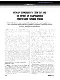
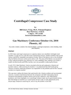
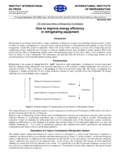
6 These can occur in any direction. Construction loads including loadout, transportation, and installation. Quasi-static skid Design focuses on evaluating stress and buckling of members, similar to static stress Design . However, fatigue analysis may be done on loads like those caused by waves. Guidelines for quasi-static skid Design include API RP 2A-WSD and International Building Code (IBC). Owners and equipment manufacturers may also have standards and specifications for both static and quasi-static loads and deflections. Figure 2. Common Reciprocating Compressor Dynamic Forces Dynamic Loads Dynamic loads can be caused by waves, wind, earthquake or machinery, but it is typically loads by the machinery itself that concern the skid designer, as it is most likely to cause resonance.
7 Resonance is the condition when the frequency of the dynamic force is within +/-10% of the mechanical natural frequency (MNF) of skid, vessels, piping, and structure/foundation. (At the Design stage, +/-20% is typically used to account for modeling and fabrication uncertainties.) Figure 2 shows common reciprocating Compressor dynamic forces, which include: Unbalanced forces created by rotating and reciprocating weights like crankshafts and piston assemblies. If the forces are offset, they can create unbalanced moments on the equipment. These can be obtained from the Compressor or engine/motor manufacturers. Unbalanced forces and moments Crosshead guide forces Cylinder horizontal gas forces Lower pressure Higher pressure Pulsation shaking forces Page 4 Horizontal cylinder gas forces, created by the differential pressure between the head end of a cylinder and the crank end.
8 Vertical forces on the crosshead guides, created when rotating motion is converted into reciprocating motion. Pulsation-induced shaking forces, created at elbows and changes in pipe diameter due to pressure pulsations. Misalignment of the Compressor and driver. Rolling torque on engines, which can occur at higher orders of engine runspeed ( , 4x, 8x, .. or 3x, 6x, ..). Torsional vibrations, which may cause horizontal vibrations of the Compressor frame. These forces are typically harmonic and occur at discrete multiples of equipment runspeed. In variable speed machines ( , motors with VFDs), the frequency of the force will change with the speed of the equipment. The majority of these forces occur at the first and second order of Compressor runspeed, so raising the mechanical natural frequencies (MNFs) of major components on the equipment package above 2x runspeed is an effective strategy for avoiding resonance.
9 Intertuning (between 1x and 2x) or detuning (below 1x) may also be possible in selected cases. In rotating equipment like motors, centrifugal compressors, and screw pumps, the dynamic forces are usually just unbalance forces and flow-induced pulsations, which tend to be low. Standards like ISO 1940/1 give recommended residual unbalance for various rotating equipment. Dynamic skid Design focuses on evaluating vibrations and fatigue. Limiting vibrations of skid members is important to limit the vibration of the equipment, vessels and piping that are attached to it. If a skid member has high vibrations then the components attached to it will likely have high vibrations also. It is important when taking vibration measurements that all components along the load path (described in Section ) are measured and compared to guideline.
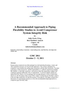
10 When discussing guidelines, it is important to distinguish been spectral and overall vibration measurements. Overall vibration measurements are the actual deflections (or velocity) of the component versus time. Spectral vibration measurements typically require specialized measuring Figure 3. EFRC Vibration Guidelines Converted to pseudo Peak Overall Velocity Page 5 equipment, which break the vibration down into peaks at discrete frequencies. It is used for troubleshooting to identify and evaluate problem areas. Vibration guidelines for skid members can vary depending on the situation. Many equipment vendors specify a maximum allowable vibration at the equipment mounting locations. A spectral guideline of in/s peak ( mm/s peak) is common.