Transcription of Machinery Vibration Limits#8
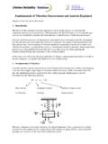
1 E:\Marketing Communications\Papers and Presentations\Technical Papers\New Technical Papers\ Machinery Vibration Limits# 1 Machinery Vibration Limits and Dynamic Structural Response By Brian C. Howes, P. Eng., Brian Howes is Manager of Engineering for Beta Machinery Analysis Ltd., Calgary. His previous experience has included research and development in the area of pulsations and vibrations of piping systems, and troubleshooting of problems in a wide range of equipment including turbines, pumps, compressors, pulp refiners, ball mills, furnaces and piping systems. He has a Master of Science in Solid Mechanics from the University of Calgary, and is a member of the Vibration Institute. ABSTRACT Changes in case Vibration readings are used to monitor rotating Machinery condition.
2 Absolute levels of Vibration are indications of condition except where structural resonances ( : bearing housings, or motor bases) amplify vibrations at certain frequencies (usually integer multiples of shaft speed). Dynamic response at Vibration test points can be measured on new installations to assist in establishing standards for absolute vibrations. Also, changes in dynamic response over time can add to understanding of machine condition. Discussion of case history to illustrate points is included. Machinery Vibration Limits and Dynamic Structural Response Vibration monitoring of rotating Machinery has developed over the years to the point where it is an accepted maintenance tool. Much effort has been applied towards developing guidelines regarding acceptable absolute levels of Vibration . Discussions of some of these standards and their inadequacies are given in References 1, 2 and 3. The real intent of Vibration monitoring, in our opinion, is to infer the absolute force levels or more basically, the stress levels, acting in the monitored machine.
3 Based on the conclusions reached from the analysis of Vibration levels, decision must be made to balance a rotor, redesign an impellor, shut a process down and open the case of a compressor, etc., all involving potentially expensive downtime of the machine. Correct analysis of the cause of high Vibration levels can permit quick correction with consequent dollar savings. Case, shaft absolute and shaft relative-to-case Vibration readings are all used for diagnosis. Structural resonances can produce local increases or decreases (Reference 1) in these Vibration levels with no change in force level in the machine. It is important to distinguish between the presence of large forces (eg: large unbalance, malalignment, high vane passing pulsations, etc.) and dynamic amplification of the internally generated forces by a structural resonance, as the type of corrective measure will be different. Three classes of problem can be envisioned: - high Vibration , acceptable forces, structural resonance - high Vibration , unacceptable forces, structural resonance - high Vibration , unacceptable forces, no structural resonance.
4 Another aspect of Vibration analysis involves the amount of prior knowledge. Two general situations occur: - troubleshooting a new problem or a newly started machine with no background Vibration data available for the machine. - trending of Vibration levels over an extended period has been carried out and is used to assist in diagnosing the cause of a problem on a machine. Although this paper is written from the first point of view, trending of vibrations would generally be preferred. Trending will detect changes in machine condition that may be very difficult to detect without historical information. An example of this concept was recently observed on a centrifugal compressor. The Vibration levels were within guideline . However, the compressor had recently lost a blade. The Vibration levels before losing the blade were significantly less than guideline . Without the historical information a case could not be made for shutting the unit down, bearing in mind the high cost of lost production during shutdown.
5 Knowledge of the dynamic stiffness of machines at the various Vibration test points can reduce the need to rely on historical data. The following case histories are provided as examples to show situations where simple measurement of vibrations and comparison with standards would have or did cause confusion and lost time in the correct diagnosis of the problem. Consider the situation in which a machine has unbalance generating 1000 lb. shaking force at operating speed of 3600 rpm. If the bearing housing has a dynamic stiffness of 1,000,000 lb/in, then the Vibration amplitude will be: 1000 inch = .001 inch = 2 mil p-p 1,000,000 or: .001 inch x 3600 x 2 rad = .377 in pk 60 sec sec Now consider a similar machine with a bearing housing having a stiffness of only 500,000 lb/in. The same unbalance would produce 4 mils p-p or.
6 75 in/sec peak. The quality of the balance of each machine is the same, yet according to the Vibration standards the second machine is in worse condition . That is has poorer balance . If one accepts that stress is proportional to Vibration , the second machine should be balanced to twice as stringent a standard as the first. This might require balancing twice as often as the first machine with proportionately higher costs of downtime. Alternatively, an increase in the dynamic stiffness of the bearing housing would make the machine less sensitive to changes in balance (eg: due to wear or buildup on the rotor over a period of time) producing operating savings at the cost of an initial capital expense. Case History 1: High Vibrations, Acceptable Forces, Structural Resonance A newly installed boiler feedwater pump was started up and found to have excessive radial vibrations on the bearing housings of the pump (over in/sec pk) primarily at vane passing frequency as well as high radial and axial vibrations on the motor at shaft frequency.
7 We were requested to analyze the problem and make recommendations. The pump purchaser was holding up the order for two more of the pumps until the problems were resolved. Upon arrival at site, we were informed that the pump had been tested at the factory (in Europe) before shipment. Vibration levels less than in/sec peak were observed and considered acceptable during the factory test. However, due to the fact that standard European power frequency is 50 Hz versus 60 Hz in North America, the factory tests had been at 3000 RPM versus 3600 RPM on site. It was concluded, after our testing, that the pump impellor design was acceptable. Several resonances were shown to be amplifying otherwise acceptable force levels. Possible courses of action for reducing the vibrations were presented to the pump end-user, who then presented our findings to the manufacturer. Description of System: The system schematic layout and operating conditions are presented in Figure 1.
8 The pump had plain journal bearings cantilevered from the main pump about 10 inches. The impellor had 4 stages with 7 vanes on each impellor. The diffusers had 6 vanes. The pumps were operating at a head of about 2160 feet of water during our tests. Based on the Pump Characteristics Curves supplied with the pump, the pump flow rate was about 800 US gpm and the pump efficiency was near optimum at 70 to 75%. No flow measurement was available in the system to confirm the flow rate estimates. The induction motor had rolling element bearings and operated at Hz (3570 RPM). Vane passing frequency was approximately 417 Hz. Testing: The Vibration levels at or near the four bearings were recorded initially. The unfiltered readings showed high vibrations, particularly on the pump inboard. These data are presented in Table 1 in terms of both velocity and acceleration. They are also presented in Figure 2 in spectral form. The coupled motor vibrations were high also as show in Figure 2.
9 Uncoupled, the motor did not run very much smoother. The uncoupled motor Vibration data are presented in Table 2 and Figure 3. The majority of the vibrations on the pump bearings were observed to be at 7 times shaft speed. This frequency coincides with vane passing frequency on the impellor. The pump body did not show high levels of Vibration . Immediately, suspicion fell on the impellor design. The pump characteristics had been extrapolated from 3000 RPM tests. Could an error have been made in the design? Were the impellors not staggered on the shaft? The buyer believed that the impellors were staggered, but we did not see the impellor to confirm this point. In an attempt to further our understanding of the pump, we measured pressure pulsations at the outlet of the pump. The spectrum of these pulsations is presented in Figure 4. Also shown on Figure 4 are dimensions associated with the pulsation measurement. The pressure transducer was located at least 43 inches from the pump impellor.
10 Calculating the speed of sound in water at 330 degrees Fahrenheit inside a pipe of non-uniform wall thickness (due to the presence of the valve) gives an approximate value of 4000 to 5000 feet per second. The wavelength of 420 Hz pulsation (7 times shaft speed) will be in the range of 150 to 100 inches, making the distance from pump to pressure transducer close to a half-wave length. Assuming the pump is a velocity source, the pressure transducer was probably near a pressure minimum in the standing wave pattern at 420 Hz throughout the discharge piping system. This means that pulsations elsewhere in the system, including in the pump could have been much larger than measured. Unfortunately, the test valve used was the only one available in the discharge piping. Reference 4 suggests that pulsations less than 3% of line pressure are acceptable in centrifugal pumps. Pulsations were less than this limit at the measurement point.