Transcription of Certain UCLA Abutment - Biomet 3i
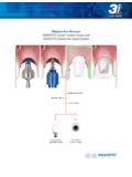
1 8 Certain UCLA AbutmentWaxing SleeveChamfer MarginImproved CylinderRetention DesignReduced Collar OSSEOTITE Certain Line of restorative componentsincludes a newly designed UCLA Abutment . This new designprovides greater predictability and more flexibility for laboratorytechnicians when waxing and casting implant level restorations. Improved Cylinder Retention DesignThe new design incorporates machined vertical grooves thatreduces the potential for miscasts due to the smoother alloyflow onto the gold alloy cylinder during casting. The verticalgrooves provide mechanical retention and are designed toeliminate the problem on previous UCLA designs of the alloystopping on the horizontal retention instead of flowing to themargin (fig. 10). Chamfer MarginThe chamfer margin design provides a smooth transitionfrom thegold alloy cylinder to the cast alloy at the junction.
2 Italso aids in theprevention of alloy flowing onto the interfacearea of the gold alloy cylinder during casting (fig. 10). Reduced Collar HeightThe collar height has been reduced from 1mm to toprovide greater flexibility when fabricating restorations forimplants with shallow tissue depths. This allows the restorationto emerge from the implant platform more quickly and to addporcelain closer to the implant platform on screw retainedrestorations (fig. 11). Collar Adjustment After CastingThe reduced collar height may cause an undercut laterallyaround the implant platform. The undercut should beremoved after casting by tapering the collar back (fig. 12).fig. 10fig. 11fig. 12 Certain UCLAS crew RetainedCrownCrown CopingCertain UCLAC ement RetainedCrownCustom Abutment9 Large Diameter Gold-Tite Abutment ScrewInternal Engagementfig.
3 13 Certain Non-Hexed UCLA Abutment4mm1mmfig. 1440 Divergence Between Splinted ImplantsThe Certain Non-hexed Abutments are designed to provideflexibility forlaboratory technicians when fabricating splinted multi-unit, screw-retained provisionals, bridge frameworks and bars for implant levelrestorations. Internal EngagementThe non-hexed abutments have a 1mm internal engagementfeature to allow a greater degree of draw from multiple divergentimplants than other internal connection implant systems (fig. 13). Large Diameter Abutment ScrewThe non-hexed abutments are retained into the implant with aunique Large Diameter Gold-Tite or Titanium Abutment Screw. Thelarger diameter screw provides lateral stability to the restoration. Itgoes into the full depth of the internal connection, replacing the4mm length of the hexed Abutment s connection (fig.)
4 13). EachCertain Non-hexed Abutment is packaged with a Large DiameterGold-Tite or Titanium Abutment Screw. Maximum Draw Of Non-Hexed AbutmentsThe non-hexed abutments have a maximum draw angle of 40 between implants (fig. 14). Gold Alloy Cylinder FormulationThe formulation specifics for the gold alloy cylinder materialused with the ucla abutments is indicated on the chart to theright. The formulation should be taken into considerationduring burnout and casting Range1400-1490 C (2550-2710 F)Solidus1400 CLiquidus1490 x 10-6 K at 500 CGOLD ALLOY CYLINDER FORMULATIONAn alloy with a CTE of x 10-6 K at 500 C is recommendedCertain Non-Hexed Abutments