Transcription of CFR Series Fan-Powered, VAV Terminals
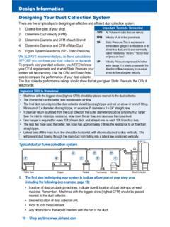
1 CFR Series Fan- powered , VAV TerminalsModel CFR construction featuresPage Trims Short (5/8") Here!Integral discharge collar simplifies field installationAll unit configurations listed with ETL for safety complianceProduct label includes tagging, airflow , and electrical informationMechanical lock construction ensures lowest possible casing leakageFull bottom removable access panelsLow leakage damper incorporates closed cell foam gasketRoll formed inlet collar with integral stiffening ribs adds strength and rigidityPatented FlowStarTM airflow sensor (Patent #5,481,925)Galvanized steel casing withstands 125 hour salt spray test per ASTM B-117 Mechanically fastened insulation for added security3/4" thick fiberglass insulation complying with UL 181, NFPA 90A, and ASTM C1071 Fan assembly utilizes a forward curved, dynamically balanced, galvanized wheel with a direct drive motorElectrical devices installed within a NEMA 1enclosure, with single point power connectionCFR Fan- powered , VAV Terminals .
2 Quiet operation, constant airflowOwnersCFR Terminals are specifically designed for quiet also offer improved space comfort and flexibility for awide variety of heating, ventilating and air-conditioning (HVAC)systems. This is critical in today s buildings where occupantsare placing more emphasis on indoor benefit from a CFR design that minimizes low-frequency (125-250 Hz) sound levels that typically dominatethe space sound flow-measuring allows control at lower minimumcubic-feet-per-minute (CFM) values, which reduces energycosts and sound levels while maintaining comfort in theoccupied to heightened interest in indoor air quality, many HVAC system designers are focusing on the effects of particulatecontamination within a building s occupied space. Often,HVAC system noise is overlooked as a source of occupied-space contamination. The CFR terminal is specifically designedto eliminate obtrusive fan noise from reaching the occupants,while providing constant air motion in the CFR terminal is manufactured and assembled with amulti-axis, multi-point, center-averaging, airflow sensor.
3 Thissensor provides a signal to the controller enabling it to quietlyand precisely measure Terminals can be used in these types of applications: Series Fan, Cooling Only Series Fan with ReheatModel CFR-EH offers electric heat and model CFR-WCoffers hot-water heat. Both are available with ElectronicallyCommutated Motor (ECM).Model CFR Terminals are available with analog-electronic,consignment-DDC, and pneumatic controls. The analog electronic controls are manufactured by Johnson Controls,and are specifically designed for use with CFR by experts in VAV- terminal operation, these controlscan accommodate a multitude of control schemes, from themost basic to the most sophisticated sequence of CFR Terminals are thoroughly inspected during each stepof the manufacturing process, including a comprehensivepre-shipment inspection, to assure the highest quality productavailable. Each unit is also run-tested, before leaving thefactory, to ensure trouble-free Terminals can be installed with metal hanging brackets, for use with all-thread support rods,or wire hangers are also single-point, power connection, and factory-calibratedcontrols, minimize installation time.
4 Electronic controls andelectrical components are located on the same side of thecasing for quick access, adjustment, and fan-speed adjustment is accomplished with an electronicSCR Terminals utilize three-tap motors that accommodatea broad range of flow and static-pressure FlowStar sensor ensures accurate airflow measurement,regardless of the installation conditions. A calibration labeland wiring diagram is located on the terminal for quickreference during Terminals require no periodic maintenance other thanoptional filter replacement. If component replacement becomesnecessary, the unit is designed to minimize field labor. The bottom casing panels can be removed to provide easy access to the fan assembly, and the motor electrical leads are easily airflow sensorNOTE: Drawings are not to scale and are not for installation purposes. Refer to for more data and dimensions are subject to change without :1. All dimensions are in inches [mm] with a tolerance of 1/8" [3mm].
5 Model CFR)Unit SizeDimensionsIABCDXYWHL0404 > @ > @ > @ > @ > @ > @ > @ > @ > @ > @0504 > @ > @ > @ > @ > @ > @ > @ > @ > @ > @0604 > @ > @ > @ > @ > @ > @ > @ > @ > @ > @0506 > @ > @ > @ > @ > @ > @ > @ > @ > @ > @0606 > @ > @ > @ > @ > @ > @ > @ > @ > @ > @0806 > @ > @ > @ > @ > @ > @ > @ > @ > @ > @0611 > @ > @ > @ > @ > @ > @ > @ > @ > @ > @0811 > @ > @ > @ > @ > @ > @ > @ > @ > @ > @1011 > @ > @ > @ > @ > @ > @ > @ > @ > @ > @0818 > @ > @ > @ > @ > @ > @ > @ > @ > @ > @1018 > @ > @ > @ > @ > @ > @ > @ > @ > @ > @1218 > @ > @ > @ > @ > @ > @ > @ > @ > @ > @1021 > @ > @ > @ > @ > @ > @ > @ > @ > @ > @1221 > @ > @ > @ > @ > @ > @ > @ > @ > @ > @1421 > @ > @ > @ > @ > @ > @ > @ > @ > @ > @1224 > @ > @ > @ > @ > @ > @ > @ > @ > @ > @1424 > @ > @ > @ > @ > @ > @ > @ > @ > @ > @1230 > @ > @ > @ > @ > @ > @ > @ > @ > @ > @1430 > @ > @ > @ > @ > @ > @ > @ > @ > @ > @1630 > @ > @ > @ > @ > @ > @ > @ > @ > @ > @1440 > @ > @ > @ > @ > @ > @ > @ >
6 @ > @ > @1640 > @ > @ > @ > @ > @ > @ > @ > @ > @ > @1644 > @ > @ > @ > @ > @ > @ > @ > @ > @ > @1844 > @ [ > @ > @ > @ > @ > @ > @ > @ > @ > @ > @LEFT SIDE VIEW(Control enclosure and filter rack not shown in this vi ew)TOP VIEW(Pneumatic controls not shown in this vi ew)INLET END VIEW(Electronic controls and filter rack not shown in this vi ew)Model CFR-EH (Electric Heat)NOTE: Drawings are not to scale and are not for installation purposes. Refer to for more data and dimensions are subject to change without CFR-WC (Hot-Water Coil)Page Trims Short (5/8") Here!Fan SizeGJKM04 > @ > @ > @ > @06, 11 > @ > @ > @ > @18, 21 > @ > @ > @ > @24 > @ > @ > @ > @30, 40 > @ > @ > @ > @44 > @ > @ > @ > @RIGHT SIDE VIEWDISCHARGE END VIEWFAN SIZES 04, 06, 11, 18, 21 AND 24 FAN SIZES 30, 40 AND 44 STANDARD FEATURES:Construction AHRI Standard 880-certified and labeled 22-gauge, galvanized-steel casing and valve 3/4 thick, fiberglass insulation, mechanically fastened for added securityHot-Water Coils 1, 2, 3, 4-row coils T ested at a minimum of 350 psig under waterFan Assemblies F orward-curved, dynamically-balanced, direct-drive, galvanized blower wheel 115 to 277-volt, single-phase, three-tap, permanent-split capacitor (PSC) motor S CR fan-speed controller Quick-select, motor-speed terminal P ermanently lubricated motor bearings Thermally protected motor Vibration-isolation motor mounts Single-point wiringPrimary Air Valve Embossed rigidity rings L ow-thermal-conductance damper shaft with position indicator Mechanical stops for open and closed position Multi-point, center-averaging, airflow sensor Balancing teesElectrical Components cETL listed for safety compliance with UL 1996 National Electrical Manufacturers Association (NEMA)]
7 Type 1 wiring enclosureElectric Heat cETL listed as an assembly for safety compliance Integral, electric-heat assembly A utomatic-reset primary and back-up secondary thermal limits Single-point-power connection Hinged, electrical-enclosure door Fusing per NEC Ni-chrome elements Wiring diagram and ETL label F an-interlock device (relay or pneumatic-electric [PE] switch)OPTIONAL FEATURES:Construction 20-gauge, galvanized-steel construction 1 insulation Scrim-reinforced, foil-faced insulation meeting American Society for Testing and Materials (ASTM) C1136 for mold, mildew, and humidity resistance 1/2 thick elastomeric closed cell foam insulation Double-wall construction with 22-gauge liner Mounting brackets to accept all threaded hanging rods or wire hangers L ow-temperature construction for use in thermal-storage applications, including a thermally-isolated, primary air inlet and a composite damper shaft L ow-velocity, low-pressure-drop, filter rack and filters located at induction inlet and/or radiated sound damper Hot -water, steam, or electric heating coils mounted at unit discharge access plate upstream of hydronic coil (standard)
8 Fan Assemblies 208, 230, 240 and 480-volt, single-phase, PSC motors 220/240-volt, 50 Hz motors 120 , 208, 240, and 277-volt ECM motorsElectrical Components Full-unit, toggle disconnect and inline motor fusing Primary and secondary transformer fusingElectric Heat Pr oportional, solid-state-relay (SSR) heater control Dis connect (toggle or door-interlocking) Pneumatic-electric (PE) switches Magnetic contactors Manual-reset secondary limit airflow switchControls F actory-provided controls include: - Pneumatic controls - Analog electronic controls Consignment DDC controls (factory-mount and wire controls provided by others)CFR terminal FeaturesENVIRO-TEC is a registered trademark of Johnson Controls, Inc. in the United States of America and other countries. Other trademarks used herein may be trademarks or registered trademarks of other (815) Supersedes PUBL-5525 (1008) 2015 Johnson Controls, Inc. Box 423, Milwaukee, WI 53201 Printed in