Transcription of Chapter 11 Transition to Complex Airplanes
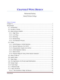
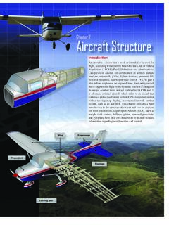
1 11-1 IntroductionA high-performance airplane is defined as an airplane with an engine capable of developing more than 200 horsepower. A Complex airplane is an airplane that has a retractable landing gear, flaps, and a controllable pitch propeller. In lieu of a controllable pitch propeller, the aircraft could also have an engine control system consisting of a digital computer and associated accessories for controlling the engine and the propeller. A seaplane would still be considered Complex if it meets the description above except for having floats instead of a retractable landing gear to Complex Airplanes Chapter 1111-2 Figure 11-2. Coefficient of lift comparison for flap extended and retracted with flap extendedAngle of attack CLCL, max flappedCL, max normalStalled airfoilNormal airfoilSimple flapped airfoilMean camber lineIncreased camberFigure 11-1.
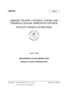
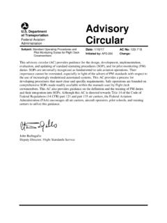
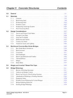
2 Airfoil to a Complex airplane, or a high-performance airplane, can be demanding for most pilots without previous experience. Increased performance and complexity both require additional planning, judgment, and piloting skills. Transition to these types of Airplanes , therefore, should be accomplished in a systematic manner through a structured course of training administered by a qualified flight can be designed to fly through a wide range of airspeeds. High speed flight requires smaller wing areas and moderately cambered airfoils whereas low speed flight is obtained with airfoils with a greater camber and larger wing area. [Figure 11-1] Many compromises are often made by designers to provide for higher speed cruise flight and low speeds for landing.
3 Flaps are a common design effort to increase an airfoil s camber and the wing s surface area for lower speed flight. [Figure 11-2]Since an airfoil cannot have two different cambers at the same time, one of two things must be done. Either the airfoil can be a compromise, or a cruise airfoil can be combined with a device for increasing the camber of the airfoil for low-speed flight. Camber is the asymmetry between the top and the bottom surfaces of an airfoil. One method for varying an airfoil s camber is the addition of trailing-edge flaps. Engineers call these devices a high-lift of FlapsFlaps work primarily by changing the camber of the airfoil which increases the wing s lift coefficient and with some flap designs the surface area of the wing is also increased.
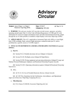
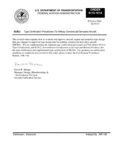
4 Flap deflection does not increase the critical (stall) angle of attack (AOA) and, in some cases, flap deflection actually decreases the critical AOA. Deflection of a wing s control surfaces, such as ailerons and flaps, alters both lift and drag. With aileron deflection, there is asymmetrical lift which imparts a rolling moment about the airplane s longitudinal axis. wing flaps acts symmetrically about the longitudinal axis producing no rolling moment; however, both lift and drag increase as well as a pitching moment about the lateral axis. Lift is a function of several variables including air density, velocity, surface area, and lift coefficient. Since flaps increase an airfoil s lift coefficient, lift is increased. [Figure 11-3]As flaps are deflected, the aircraft may pitch nose up, nose down or have minimal changes in pitch attitude.
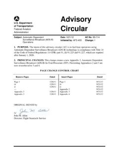
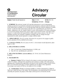
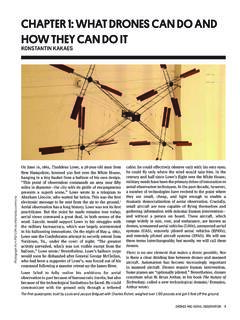
5 Pitching moment is caused by the rearward movement of the wing s center of pressure; however, that pitching behavior depends on several variables including flap type, wing position, downwash behavior, and horizontal tail location. 11-3 Figure 11-4. Four basic types of 11-3. Lift equation. L = 1 pV 2 SCL2L = Lift producedP = Air densityV = Velocity relative to the airS = Surface area of the wingCL = lift coefficient which is determined by the camber of the airfoil used, the chord of the wing and AOAP lain flapSplit flapSlotted flapFowler flapConsequently, pitch behavior depends on the design features of the particular deflection of up to 15 primarily produces lift with minimal increases in drag. Deflection beyond 15 produces a large increase in drag.
6 Drag from flap deflection is parasite drag and, as such, is proportional to the square of the speed. Also, deflection beyond 15 produces a significant nose-up pitching moment in most high- wing Airplanes because the resulting downwash increases the airflow over the horizontal EffectivenessFlap effectiveness depends on a number of factors, but the most noticeable are size and type. For the purpose of this Chapter , trailing edge flaps are classified as four basic types: plain (hinge), split, slotted, and Fowler. [Figure 11-4]The plain or hinge flap is a hinged section of the wing . The structure and function are comparable to the other control surfaces ailerons, rudder, and elevator. The split flap is more Complex . It is the lower or underside portion of the wing ; deflection of the flap leaves the upper trailing edge of the wing undisturbed.
7 It is, however, more effective than the hinge flap because of greater lift and less pitching moment, but there is more drag. Split flaps are more useful for landing, but the partially deflected hinge flaps have the advantage in takeoff. The split flap has significant drag at small deflections, whereas the hinge flap does not because airflow remains attached to the slotted flap has a gap between the wing and the leading edge of the flap. The slot allows high-pressure airflow on the wing undersurface to energize the lower pressure over the top, thereby delaying flow separation. The slotted flap has greater lift than the hinge flap but less than the split flap; but, because of a higher lift-drag ratio, it gives better takeoff and climb performance.
8 Small deflections of the slotted flap give a higher drag than the hinge flap but less than the split. This allows the slotted flap to be used for Fowler flap deflects down and aft to increase the wing area. This flap can be multi-slotted making it the most Complex of the trailing-edge systems. This system does, however, give the maximum lift coefficient. Drag characteristics at small deflections are much like the slotted flap. Fowler flaps are most commonly used on larger Airplanes because of their structural complexity and difficulty in sealing the ProceduresIt would be impossible to discuss all the many airplane design and flap combinations. This emphasizes the importance of the Federal Aviation Administration (FAA) approved Airplane Flight Manual and/or Pilot s Operating Handbook (AFM/POH) for a given airplane.
9 While some AFM/POHs are specific as to operational use of flaps, others leave the use of flaps to pilot discretion. Hence, flap operation makes pilot judgment of critical importance. Since flap operation is used for landings and takeoffs, during which the airplane is in close proximity to the ground where the margin for error is small. Since the recommendations given in the AFM/POH are based on the airplane and the flap design , the pilot must relate the manufacturer s recommendation to aerodynamic effects of flaps. This requires basic background knowledge of flap aerodynamics and geometry. With this information, a decision as to the degree of flap deflection and time of deflection based on runway and approach conditions relative to the wind conditions can be time of flap extension and degree of deflection are related.
10 Large flap deflections at one single point in the landing pattern produce large lift changes that require significant pitch and power changes in order to maintain airspeed and glide slope. Incremental deflection of flaps on downwind, base, and final approach allow smaller adjustment of pitch and power compared to extension of full flaps all at one time. This procedure facilitates a more stabilized all landings should be accomplished at the slowest speed possible for a given situation, a soft or short-field landing requires minimal speed at touchdown while a short field obstacle approach requires minimum speed and a steep approach angle. Flap extension, particularly beyond 30 , results in significant levels of drag.