Transcription of CHAPTER 15 DISTRIBUTION TRANSFORMERS
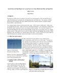
1 13/07/06 11:43AM Page CHAPTER 15. DISTRIBUTION . TRANSFORMERS . The purpose of a DISTRIBUTION transformer is to reduce the primary voltage of the electric DISTRIBUTION system to the utilization voltage serving the customer. A DISTRIBUTION trans- former is a static device constructed with two or more windings used to transfer alternating- current electric power by electromagnetic induction from one circuit to another at the same frequency but with different values of voltage and current. Figure shows DISTRIBUTION TRANSFORMERS in stock at an electric utility company ser- vice building. The DISTRIBUTION TRANSFORMERS available for use for various applications, as shown, include pole-type (Figs. and ), pad-mounted (Fig. ), vault or network type (Fig. ), and submersible (Fig. ). The DISTRIBUTION transformer in Fig. is self-protected. It is equipped with a lightning arrester, a weak-link or protective-link expulsion-type fuse (installed under oil in the trans- former tank), a secondary circuit breaker, and a warning light.
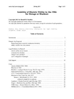
2 The transformer primary bushing conductor is connected to one phase of the three-phase primary circuit through a partial-range current-limiting fuse. The transformer tank is grounded and connected to the FIGURE Electric utility DISTRIBUTION storage yard. Forklift trucks are used to load TRANSFORMERS on line trucks. Storage area is covered with concrete to pro- vide accessibility and protect TRANSFORMERS . 13/07/06 11:43AM Page CHAPTER 15. FIGURE Typical pole-type dis- tribution transformer installation with the transformer bolted directly to the pole. The unit is equipped with a surge arrester, a low-voltage circuit breaker, and an overload warning light. A partial- range current-limiting fuse is mounted on the primary bushing, connecting it in series with the high-voltage winding to prevent a violent failure of the trans- former if an internal fault develops. primary and secondary common-neutral ground wire.
3 The self-protected transformer con- tains a core and coils, a primary fuse mounted on the bottom of the primary bushing, a sec- ondary terminal block, and a low-voltage circuit breaker. Convential overhead TRANSFORMERS are also available. The key component distinguish- ing the conventional transformer from the self-protected transformer is the lack of internal fusing in the conventional model. An external fuse/cutout combination is mounted between the DISTRIBUTION primary and the conventional transformer. A conventional unit is depicted in Fig. Pad-mounted TRANSFORMERS are used with underground systems. Three-phase pad- mounted TRANSFORMERS are used for commercial installations, as illustrated in Fig. , and single-phase pad-mounted TRANSFORMERS are used for underground residential installations, as described and shown in Chap. 34. Vault-type DISTRIBUTION TRANSFORMERS are installed for commercial customers where adequate space is not available for pad-mounted transform- ers.
4 The vault-type transformer (Fig. ) may be installed in a vault under a sidewalk or in a building. They are often used in underground electric network areas. Submersible single-phase DISTRIBUTION TRANSFORMERS (Fig. ) are used in some under- ground systems installed in residential areas, as described in Chap. 34. Corrosion problems and the high cost of installation have minimized the use of submersible TRANSFORMERS . DISTRIBUTION Transformer Operation. The basic principle of operation of a transformer is explained in Chap. 1. A schematic drawing of a single-phase DISTRIBUTION transformer appears in Fig. The single-phase DISTRIBUTION transformer consists of a primary wind- ing and a secondary winding wound on a laminated steel core. If the load is disconnected from the secondary winding of the transformer and a high voltage is applied to the primary winding of the transformer, a magnetizing current will flow in the primary winding.
5 If we assume the resistance of the primary winding is small, which is usually true, this current is limited by the countervoltage of self-induction induced in the highly inductive primary 13/07/06 11:43AM Page DISTRIBUTION TRANSFORMERS FIGURE Two view construction standard detail of a conventional transformer to be installed on the DISTRIBUTION system. Note the fused cutout and lighting arrestor combination external to the transformer. (Courtesy MidAmerican Energy Co.). FIGURE Three-phase pad-mounted transformer installed in shopping center parking lot. Transformer reduces voltage from 13,200Y/7620 to 208Y/120 volts. Primary and secondary terminals of trans- former are connected to underground cables. (Courtesy ABB Power T&D. Company Inc.). 13/07/06 11:43AM Page CHAPTER 15. FIGURE Vault-type DISTRIBUTION transformer FIGURE Submersible DISTRIBUTION transformer 1000 kVA, three-phase 13,200 GrdY/7620 to strapped to a pallet for shipment.
6 Cables are for low- 208Y/120 volts. High-voltage terminals H1, H2, and voltage connections. High-voltage connections are H3 are designed for elbow-type cable connections, made with elbow cable connectors to bushing inserts and low-voltage terminals X1, X2, and X3 are spade- installed in wells shown on top of the transformer. type for bolted connections to cable lugs. (Courtesy (Courtesy ABB Power T&D Company Inc.). ABB Power T&D Company Inc.). winding. The windings of the transformer are constructed with sufficient turns in each winding to limit the no-load or exciting current and produce a countervoltage approxi- mately equal to the applied voltage. The exciting current magnetizes, or produces a mag- netic flux in the steel transformer core. The magnetic flux reverses each half cycle as a result of the alternating voltage applied to the primary winding. The magnetic flux pro- duced cuts the turns of the primary and secondary windings.
7 This action induces a coun- tervoltage in the primary winding and produces a voltage in the secondary winding. The voltages induced in each turn of the primary and secondary winding coils will be approxi- mately equal, and the voltage induced in each winding will be equal to the voltage per turn multiplied by the number of turns. Voltage V = volts per turn number of turns N. Voltage primary winding = Vp Voltage secondary winding = Vs Volts per turn = Vt FIGURE Schematic drawing of single-phase distribu- tion transformer. 13/07/06 11:43AM Page DISTRIBUTION TRANSFORMERS Number of turns of primary winding = Np Number of turns of secondary winding = Ns Therefore, the voltage of the primary winding is equal to the applied voltage and equal to the number of turns in the primary winding multiplied by the volts per turn. Vp Vt Np Likewise the voltage of the secondary winding will equal the volts per turn multiplied by the number of turns in the secondary winding.
8 Vs Vt Ns If we use basic algebraic operations and divide both sides of an equation by the same num- ber, we can obtain the following equation: Vp Vt Np . Np Np Vp Vt Np and Vs Vt Ns . Ns Ns Vs Vt Ns Quantities equal to the same quantity are equal, so Vp Vs . Np Ns Both of the above quantities are equal to Vt. If we multiply both sides of the equation by the same quantity Np, we obtain Vp Vs Np Np . Np Ns or Np Vp Vs Ns Likewise, Ns Vs Vp Np Therefore, if we know the source voltage, or primary voltage, and the number of turns in the primary and secondary windings, we can calculate the secondary voltage. For exam- ple, if a DISTRIBUTION transformer has a primary winding with 7620 turns and a secondary winding of 120 turns and the source voltage equals 7620 volts, the secondary voltage equals 120 volts. 13/07/06 11:43AM Page CHAPTER 15. Ns Vs Vp . Np 120. 7620 volts 7620.
9 120 volts When a load is connected to the secondary winding of the transformer, a current Is will flow in the secondary winding of the transformer. This current is equal to the secondary voltage divided by the impedance of the load Z. Vs Is . Z. Lenz' law determined that any current that flows as a result of an induced voltage will flow in a direction to oppose the action that causes the voltage to be induced. Therefore, the secondary current, or load current, in the DISTRIBUTION transformer secondary wind- ing will flow in a direction to reduce the magnetizing action of the exciting current or the primary current. This action reduces the magnetic flux in the laminated steel core momentarily and, therefore, reduces the countervoltage in the primary winding. Reducing the countervoltage in the primary winding causes a larger primary current to flow, restoring the magnetic flux in the core to its original value.
10 The losses in a distri- bution transformer are small, and therefore, for all practical purposes, the voltamperes of the load, or secondary winding, equal the voltamperes of the source, or primary winding. Vp Ip Vs Is If we divide both sides of this equation by the same quantity Vp, we obtain Vp Ip Vs Is . Vp Vp or Vs Ip Is Vp Therefore, if the primary source voltage of a transformer is 7620 volts, the secondary volt- age is 120 volts, and the secondary current, as a result of the load impedance, is 10 amps, then the primary current is amp. 120. Ip 10 amp 7620. A three-phase transformer is basically three single-phase TRANSFORMERS in a single tank in most cases. The windings of the three TRANSFORMERS are normally wound on a single mul- tilegged laminated steel core. Amorphous Metal. Some DISTRIBUTION TRANSFORMERS are being manufactured with amor- phous metal cores. The amorphous metal reduces the core loss in a DISTRIBUTION transformer, thus increasing the transformer efficiency.