Transcription of SECTION 22 POWER ELECTRONICS - books.mhprofessional.com
1 17/7/06 8:58 PM Page 22-1. SECTION 22. POWER ELECTRONICS . Amit Kumar Jain Engineering Technical Staff, Analog POWER Design Inc. Raja Ayyanar Associate Professor, Department of Electrical Engineering, Arizona State University CONTENTS. INTRODUCTION ..22-2. Role of POWER electronic Converters ..22-2. Application Examples ..22-2. Scope and Organization ..22-4. PRINCIPLES OF SWITCHED MODE POWER . CONVERSION ..22-4. Bipositional Switch ..22-4. Pulse Width Modulation ..22-5. Concept of Steady State ..22-6. POWER Loss in the Bipositional Switch ..22-8. DC-DC CONVERTERS ..22-9. Buck Converter ..22-9. Boost Converter ..22-12. Flyback Converter ..22-13. Full-Bridge DC-DC Converter ..22-14. Other Isolated DC-DC Converters ..22-14. Recent Developments and Future Trends ..22-16. FEEDBACK CONTROL OF POWER . electronic CONVERTERS ..22-16. Dynamic Modeling.
2 22-17. Control Design ..22-19. Current Mode Control ..22-21. Other Control Techniques ..22-21. DC-AC CONVERSION: INVERSION ..22-22. Single Phase AC Synthesis ..22-22. Three-Phase AC Synthesis ..22-25. Space Vector Modulation ..22-26. Multilevel Converters ..22-27. AC-DC CONVERSION: RECTIFICATION ..22-30. Single-Phase Diode Bridge Rectifier ..22-30. Three-Phase Diode Bridge Rectifier ..22-32. Controlled Thyristor Rectifiers ..22-34. AC TO AC CONVERSION ..22-35. PROBLEMS CAUSED BY POWER electronic . CONVERTERS AND SOLUTIONS ..22-37. Harmonics and POWER Factor Correction ..22-37. Electromagnetic Interference ..22-40. APPLICATIONS OF POWER electronic . CONVERTERS ..22-41. DC POWER Supplies ..22-41. Electric Drives ..22-42. Battery Charging ..22-45. 22-1. 17/7/06 8:58 PM Page 22-2. 22-2 SECTION TWENTY-TWO. Fluorescent Lamps and Solid State Lighting.
3 22-46. Automotive Applications ..22-47. UTILITY APPLICATIONS OF POWER ELECTRONICS .22-47. Introduction ..22-47. Flexible AC Transmission Systems ..22-48. Custom POWER ..22-53. Distribution Generation Interface ..22-55. COMPONENTS OF POWER electronic . CONVERTERS ..22-57. POWER Semiconductor Devices ..22-57. Magnetic Components ..22-60. Capacitors ..22-63. Snubber Circuits ..22-63. Heat Sinks ..22-64. REFERENCES ..22-65. INTRODUCTION. Role of POWER electronic Converters POWER ELECTRONICS is an enabling technology that achieves conversion of electric POWER from one form to another, using a combination of high- POWER semiconductor devices and passive components chiefly transformers, inductors, and capacitors. The input and output may be alternating current (ac) or direct current (dc) and may differ in magnitude and frequency. The conversion sometimes involves multiple stages with two or more converters connected in a cascade.
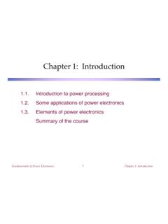
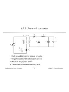
4 The end goals of a POWER electronic con- verter are to achieve high efficiency of conversion, minimize size and weight, and achieve desired regu- lation of the output. Figure 22-1 shows POWER electronic converters in a generic application. Application Examples POWER electronic converters can be classified into four different types on the basis of input and out- put, dc-dc, dc-ac, ac-dc, and ac-ac, named with the first part referring to the input and the second to the output. The diode bridge rectifier is the front end for most low- POWER converters. It converts line frequency ac ( , from a wall outlet) to an unregulated dc voltage, and the process is commonly called rectification. In a dc-dc converter, both the input and the output are dc, and in the simplest case the output voltage needs to be regulated in presence of variation in load current and changes in the input voltage.
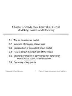
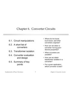
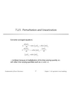
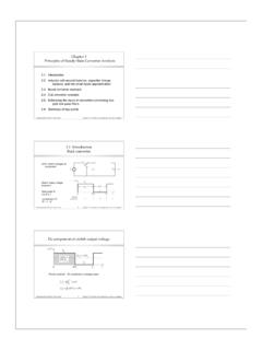
5 A computer POWER supply has a diode bridge front end followed by a dc-dc converter, the combination of which converts line frequency ac voltage to several regulated dc voltages (Fig. 22-2). electronic ballasts for compact fluorescent lamps consist of a line frequency rectifier followed by a dc to high-frequency ac converter (frequency range of 20 to 100 kHz) whose output is connected to a resonant tank circuit that includes the load. In an adjustable speed motor drive application (Fig. 22-3), the input is a 3-phase ac supply, and the output is a 3-phase ac whose magnitude and frequency are varied for optimum steady-state operation and dynamic requirements of the drive. FIGURE 22-1 Application of POWER electronic converters. 17/7/06 8:58 PM Page 22-3. POWER ELECTRONICS 22-3. FIGURE 22-2 Computer POWER supply. Development of POWER semiconductors with very high voltage and current ratings has enabled the use of POWER electronic converters for utility applications.
6 In transmission systems, POWER electronic converters are being utilized to control POWER flow, damp POWER oscillations, and enhance system sta- bility. At the distribution level, POWER electronic converters are used for enhancing POWER quality by means of dynamic voltage restorers, static var compensators, and active filters. POWER electronic con- verters also play a significant role in grid connection of distributed generation and especially renewable energy sources; their functions include compensation for steady state and dynamic source characteris- tics leading to optimal energy transfer from the source, and protective action during contingencies. Future automotives are expected to have a large number of POWER electronic converters perform- ing various functions, for example, electric POWER steering, active suspension, control over various loads, and transferring POWER between the conventional 14-V bus and the recently proposed 42-V.
7 POWER Net [1]. Hybrid electric and all-electric vehicles also utilize controlled POWER electronic converters for interfacing the battery and motor/generator. The proliferation of POWER ELECTRONICS connected to the utility grid has also led to POWER quality concerns due to injection of harmonic currents by grid-connected inverters, and highly distorted currents drawn by diode bridge rectifiers. Due to fast transients of voltages and currents within POWER FIGURE 22-3 Adjustable speed motor drive. 17/7/06 8:58 PM Page 22-4. 22-4 SECTION TWENTY-TWO. converters, they can be a source of electromagnetic emissions leading to electromagnetic interference. Several solutions to limit and correct these effects have therefore been developed. Scope and Organization This SECTION gives an overview of POWER electronic systems. Details of specific converter types and applications have been omitted and only the fundamentals are presented.
8 In some cases, important results are stated without derivation. Mathematical content has been kept to a minimum. In places, empirical aspects have been included, since POWER ELECTRONICS is an application-oriented discipline. Design procedures are presented with only those justifications that were deemed imperative. A long list of references consisting of textbooks on the subject of POWER ELECTRONICS , reference books on spe- cific areas and applications of POWER ELECTRONICS , important research publications, and several online sources has been provided. The reader is expected to use this SECTION as a starting point, followed by the references on the topic of particular interest. First, the basic principles for analysis and design of POWER converters are presented in Sec. Topology and operating principles of the four types of POWER ELECTRONICS converters are described with one SECTION devoted to each.
9 A very simple description of POWER electronic converter control is pre- sented using the example of dc-dc converters. This is followed by deleterious effects of POWER elec- tronic converters and precautions necessary to limit or correct them. Applications are described next bringing together the requirements and complete POWER electronic system realization for some spe- cific examples. Finally, the individual components that constitute a POWER electronic converter are dis- cussed. Current research initiatives and expected future trends are indicated in each SECTION . PRINCIPLES OF SWITCHED MODE POWER CONVERSION. This SECTION presents some basic principles that are common to the analysis of all switch mode POWER converters. Line-commutated POWER electronic converters are not, strictly speaking, switched mode converters; they are discussed in Sec.
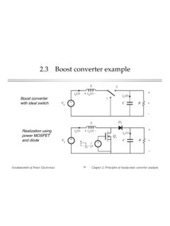
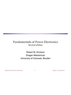
10 Bipositional Switch The most basic component of a switch mode POWER converter is the bipositional switch shown in Fig. 22-4a. Nodes 1 and 2 of the switch are invariably connected across a dc voltage source (or across FIGURE 22-4 (a) Bipositional switch (b) switching waveforms. 17/7/06 8:58 PM Page 22-5. POWER ELECTRONICS 22-5. TABLE 22-1 States of a Bipositional Switch qA(t) Switch MOSFET & Pole voltage &. position diode state input current 1 1 S1 & D1 ON, S2 & D2 OFF A Vin, iin iA. 0 2 S1 & D1 OFF, S2 & D2 ON A 0, iin 0. a big capacitor whose voltage is close to a constant dc), and pole A of the switch is in series with a dc current source (or a big inductor whose current is close to a constant dc). This bipositional switch, which is also referred to as a switching POWER pole, switches at very high frequencies, and is con- trolled by the signal qA(t).