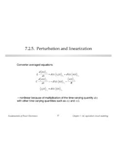
Transcription of Chapter 1: Introduction
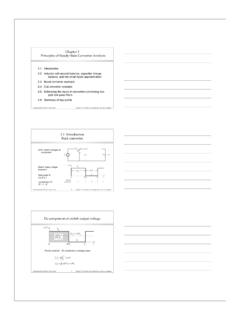
1 Chapter 1: Introduction Introduction to power processing Some applications of power electronics Elements of power electronics Summary of the course fundamentals of power electronics 2 Chapter 1: Introduction Introduction to power Processing power Switching power input converter output Control input Dc-dc conversion: Change and control voltage magnitude Ac-dc rectification: Possibly control dc voltage, ac current Dc-ac inversion: Produce sinusoid of controllable magnitude and frequency Ac-ac cycloconversion: Change and control voltage magnitude and frequency fundamentals of power electronics 3 Chapter 1: Introduction Control is invariably required power Switching power input converter output Control input feedforward feedback Controller reference fundamentals of power electronics 4 Chapter 1: Introduction High efficiency is essential 1. Pout = . Pin 1 1.
2 Ploss = Pin Pout = Pout . High efficiency leads to low power loss within converter Small size and reliable operation is then feasible Efficiency is a good measure of converter performance 0 1 Ploss / Pout fundamentals of power electronics 5 Chapter 1: Introduction A high-efficiency converter Pin Pout Converter A goal of current converter technology is to construct converters of small size and weight, which process substantial power at high efficiency fundamentals of power electronics 6 Chapter 1: Introduction Devices available to the circuit designer +.. DTs s T. Linear- mode Switched-mode Resistors Capacitors Magnetics Semiconductor devices fundamentals of power electronics 7 Chapter 1: Introduction Devices available to the circuit designer +.. DTs s T. Linear- mode Switched-mode Resistors Capacitors Magnetics Semiconductor devices Signal processing: avoid magnetics fundamentals of power electronics 8 Chapter 1: Introduction Devices available to the circuit designer +.
3 DTs s T. Linear- mode Switched-mode Resistors Capacitors Magnetics Semiconductor devices power processing: avoid lossy elements fundamentals of power electronics 9 Chapter 1: Introduction power loss in an ideal switch Switch closed: v(t) = 0 +. i(t). Switch open: i(t) = 0. v(t). In either event: p(t) = v(t) i(t) = 0. Ideal switch consumes zero power . fundamentals of power electronics 10 Chapter 1: Introduction A simple dc-dc converter example I. 10A. +. Vg + Dc-dc converter R V. 5 50V. 100V.. Input source: 100V. Output load: 50V, 10A, 500W. How can this converter be realized? fundamentals of power electronics 11 Chapter 1: Introduction Dissipative realization Resistive voltage divider I. 10A. +. + 50V . Vg + Ploss = 500W R V. 5 50V. 100V.. Pin = 1000W Pout = 500W. fundamentals of power electronics 12 Chapter 1: Introduction Dissipative realization Series pass regulator: transistor operates in active region I.
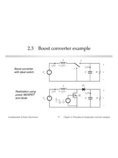
4 + 50V 10A. +. Vg linear amplifier + Vref + R V. and base driver 100V 5 50V. Ploss 500W.. Pin 1000W Pout = 500W. fundamentals of power electronics 13 Chapter 1: Introduction Use of a SPDT switch I. 1 10 A. + +. Vg 2. + vs(t) R v(t). 50 V. 100 V.. vs(t). Vg Vs = DVg 0. DTs (1 D) Ts t switch position: 1 2 1. fundamentals of power electronics 14 Chapter 1: Introduction The switch changes the dc voltage level vs(t). Vg D = switch duty cycle Vs = DVg 0 D 1. 0. Ts = switching period DTs (1 D) Ts t switch position: fs = switching frequency 1 2 1. = 1 / Ts DC component of vs(t) = average value: Ts Vs = 1 vs(t) dt = DVg Ts 0. fundamentals of power electronics 15 Chapter 1: Introduction Addition of low pass filter Addition of (ideally lossless) L-C low-pass filter, for removal of switching harmonics: 1. i(t). + +. L. Vg 2. + vs(t) C R v(t).. 100 V.. Pin 500 W Pout = 500 W.
5 Ploss small Choose filter cutoff frequency f0 much smaller than switching frequency fs This circuit is known as the buck converter . fundamentals of power electronics 16 Chapter 1: Introduction Addition of control system for regulation of output voltage power Switching converter Load input +. i vg + v . Sensor H(s) gain Transistor Error gate driver signal Pulse-width vc G (s) ve + Hv (t) modulator c Compensator Reference dTs Ts t input vref fundamentals of power electronics 17 Chapter 1: Introduction The boost converter 2. +. L. 1. Vg + C R V.. 5Vg 4Vg 3Vg V. 2Vg Vg 0. 0 1. D. fundamentals of power electronics 18 Chapter 1: Introduction A single-phase inverter vs(t). 1 + 2. Vg +. + v(t) . 2 1. load vs(t) H-bridge . Modulate switch duty cycles to obtain sinusoidal t low-frequency component fundamentals of power electronics 19 Chapter 1: Introduction Several applications of power electronics power levels encountered in high-efficiency converters less than 1 W in battery-operated portable equipment tens, hundreds, or thousands of watts in power supplies for computers or office equipment kW to MW in variable-speed motor drives 1000 MW in rectifiers and inverters for utility dc transmission lines fundamentals of power electronics 20 Chapter 1: Introduction A laptop computer power supply system Inverter Display backlighting iac(t) Charger Buck Microprocessor vac(t) PWM converter Rectifier power management ac line input Boost Disk 85 265 Vrms Lithium battery converter drive fundamentals of power electronics 21 Chapter 1.
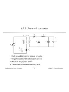
6 Introduction power system of an earth-orbiting spacecraft Dissipative shunt regulator +. Solar array vbus . Battery Dc-dc Dc-dc charge/discharge converter converter controllers Batteries Payload Payload fundamentals of power electronics 22 Chapter 1: Introduction An electric vehicle power and drive system ac machine ac machine Inverter Inverter control bus battery P. + system controller 3 ac line Battery charger DC-DC. vb converter 50/60 Hz Vehicle electronics Low-voltage dc bus Inverter Inverter Variable-frequency Variable-voltage ac ac machine ac machine fundamentals of power electronics 23 Chapter 1: Introduction Elements of power electronics power electronics incorporates concepts from the fields of analog circuits electronic devices control systems power systems magnetics electric machines numerical simulation fundamentals of power electronics 24 Chapter 1: Introduction Part I.
7 Converters in equilibrium Inductor waveforms Averaged equivalent circuit D' VD. vL(t) RL D Ron D' RD D' : 1. Vg V. +.. +. DTs D'Ts t Vg + V R. V I. switch position: 1 2 1 . iL(t). iL(DTs). iL. Predicted efficiency I. iL(0) Vg V V. 100%. L L 90%. 80%. 0 DTs Ts t 70% 60% 50% RL/R = 40%. Discontinuous conduction mode 30%. 20%. Transformer isolation 10%. 0%. 0 1. D. fundamentals of power electronics 25 Chapter 1: Introduction Switch realization: semiconductor devices iA(t). The IGBT collector Switching loss transistor waveforms Qr Vg gate iL. vA(t). 0 0. emitter t Emitter iB(t). diode waveforms iL. vB(t). Gate 0 0. t area Qr Vg n n n n p p minority carrier n- injection tr p pA(t). = vA iA. area ~QrVg Collector area ~iLVgtr t0 t1 t2 t fundamentals of power electronics 26 Chapter 1: Introduction Part I. Converters in equilibrium 2. Principles of steady state converter analysis 3.
8 Steady-state equivalent circuit modeling, losses, and efficiency 4. Switch realization 5. The discontinuous conduction mode 6. Converter circuits fundamentals of power electronics 27 Chapter 1: Introduction Part II. Converter dynamics and control Closed-loop converter system Averaging the waveforms power Switching converter Load gate input drive +. vg(t) + v(t) R.. feedback connection t . transistor actual waveform v(t). gate driver compensator including ripple (t) pulse-width vc G (s) + v modulator c averaged waveform <v(t)>Ts with ripple neglected (t) vc(t) voltage reference vref t dTs Ts t t Controller Vg V d(t). L. 1:D D' : 1. +.. +. Small-signal +. averaged vg(t). I d(t) I d(t) C v(t) R. equivalent circuit . fundamentals of power electronics 28 Chapter 1: Introduction Part II. Converter dynamics and control 7. Ac modeling 8. Converter transfer functions 9.
9 Controller design 10. Input filter design 11. Ac and dc equivalent circuit modeling of the discontinuous conduction mode 12. Current-programmed control fundamentals of power electronics 29 Chapter 1: Introductio