Transcription of Chapter 6. Converter Circuits
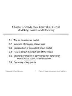
1 Chapter 6. Converter Circuits Where do the boost, circuit manipulations buck-boost, and other converters originate? A short list of How can we obtain a converters Converter having given desired properties? Transformer isolation What converters are Converter evaluation possible? and design How can we obtain transformer isolation in a Summary of key Converter ? points For a given application, which Converter is best? fundamentals of power Electronics 1 Chapter 6: Converter Circuits circuit Manipulations L. 1. +. 2. Vg + C R V.. Begin with buck Converter : derived in Chapter 1 from first principles Switch changes dc component, low-pass filter removes switching harmonics Conversion ratio is M = D. fundamentals of power Electronics 2 Chapter 6: Converter Circuits Inversion of source and load Interchange power input and output ports of a Converter Buck Converter example V2 = DV1.
2 Port 1 Port 2. L. 1. + +. 2. + V1 V2.. power flow fundamentals of power Electronics 3 Chapter 6: Converter Circuits Inversion of source and load Interchange power source and load: Port 1 Port 2. L. 1. + +. 2. V1 V2 +.. power flow V2 = DV1 V1 = 1 V2. D. fundamentals of power Electronics 4 Chapter 6: Converter Circuits Realization of switches as in Chapter 4. Port 1 Port 2. Reversal of power L. flow requires new realization of + +. switches V1 V2 +.. Transistor conducts when switch is in . position 2. Interchange of D power flow and D'. V1 = 1 V2 Inversion of buck Converter yields boost Converter D'. fundamentals of power Electronics 5 Chapter 6: Converter Circuits Cascade connection of converters Converter 1 + Converter 2 +. Vg + V1 V. V1 V = M (D). = M 1(D) V1 2. Vg . D. V1 = M 1 (D)Vg V = M(D) = M (D)M (D).
3 Vg 1 2. V = M 2 (D)V1. fundamentals of power Electronics 6 Chapter 6: Converter Circuits Example: buck cascaded by boost L1 L2 2. 1. + +. 2 1. Vg + C1 V1 C2 R V.. {. {. Buck Converter Boost Converter V1. =D. Vg V = D. Vg 1 D. V = 1. V1 1 D. fundamentals of power Electronics 7 Chapter 6: Converter Circuits Buck cascaded by boost: simplification of internal filter Remove capacitor C1. L1 L2 2. 1. +. 2 1. Vg + C2 R V.. Combine inductors L1 and L2. 1 L iL 2. +. 2 1 Noninverting +. Vg . V buck-boost Converter . fundamentals of power Electronics 8 Chapter 6: Converter Circuits Noninverting buck-boost Converter 1 L iL 2. +. 2 1. Vg + V.. subinterval 1 subinterval 2. + +. iL. Vg + V Vg + V.. iL.. fundamentals of power Electronics 9 Chapter 6: Converter Circuits Reversal of output voltage polarity subinterval 1 subinterval 2.}}
4 + +. iL. Vg + V Vg + V. noninverting . buck-boost iL.. + iL +. iL. inverting Vg + V Vg + V.. buck-boost . fundamentals of power Electronics 10 Chapter 6: Converter Circuits Reduction of number of switches: inverting buck-boost Subinterval 1 Subinterval 2. + iL +. iL. Vg + V Vg + V.. One side of inductor always connected to ground hence, only one SPDT switch needed: 1 2 +. iL V = D. Vg + V Vg 1 D.. fundamentals of power Electronics 11 Chapter 6: Converter Circuits Discussion: cascade connections Properties of buck-boost Converter follow from its derivation as buck cascaded by boost Equivalent circuit model: buck 1:D transformer cascaded by boost D':1 transformer Pulsating input current of buck Converter Pulsating output current of boost Converter Other cascade connections are possible Cuk Converter : boost cascaded by buck fundamentals of power Electronics 12 Chapter 6: Converter Circuits Rotation of three-terminal cell e-t er mi na l ce Treat inductor and T hre ll SPDT switch as three- A a 1 b B.
5 Terminal cell: +. 2. Vg + v c C.. Three-terminal cell can be connected between source and load in three nontrivial distinct ways: a-A b-B c-C buck Converter a-C b-A c-B boost Converter a-A b-C c-B buck-boost Converter fundamentals of power Electronics 13 Chapter 6: Converter Circuits Rotation of a dual three-terminal network A capacitor and SPDT - t er m i n a l ree c Th switch as a three- el l 1. terminal cell: A a b B +. 2. Vg + v . c C . Three-terminal cell can be connected between source and load in three nontrivial distinct ways: a-A b-B c-C buck Converter with L-C input filter a-C b-A c-B boost Converter with L-C output filter a-A b-C c-B Cuk Converter fundamentals of power Electronics 14 Chapter 6: Converter Circuits Differential connection of load to obtain bipolar output voltage dc source load Converter 1 +.
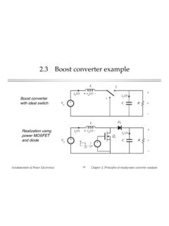
6 V1 Differential load V1 = M(D) Vg + voltage is . V. V = V1 V2.. Vg + D. The outputs V1 and V2. may both be positive, Converter 2 but the differential + output voltage V can be V2 positive or negative. V2 = M(D') Vg . D'. fundamentals of power Electronics 15 Chapter 6: Converter Circuits Differential connection using two buck converters Buck Converter 1. }. 1. + Converter #1 transistor 2. V1 driven with duty cycle D. +. Converter #2 transistor V driven with duty cycle +. complement D'. Vg . Differential load voltage 2 is 1. + V = DVg D'V g V2. Simplify: . V = (2D 1)Vg {. Buck Converter 2. fundamentals of power Electronics 16 Chapter 6: Converter Circuits Conversion ratio M(D), differentially-connected buck converters V = (2D 1)Vg M(D). 1. 0. 1 D. 1. fundamentals of power Electronics 17 Chapter 6: Converter Circuits Simplification of filter circuit , differentially-connected buck converters Original circuit Bypass load directly with capacitor Buck Converter 1.
7 } 1. 2. +. V1.. +. 1. 2. +. V V.. Vg + Vg +.. 2 2. +. 1 1. V2.. {. Buck Converter 2. fundamentals of power Electronics 18 Chapter 6: Converter Circuits Simplification of filter circuit , differentially-connected buck converters Combine series-connected Re-draw for clarity inductors 1. C. 1 L 2. Vg +. 2 + V . iL. 2 1. R. +. + V. Vg . H-bridge, or bridge inverter 2. Commonly used in single-phase 1. inverter applications and in servo amplifier applications fundamentals of power Electronics 19 Chapter 6: Converter Circuits Differential connection to obtain 3 inverter With balanced 3 load, dc source 3 ac load neutral voltage is Converter 1 +. V1 Vn = 1 V1 + V2 + V3. V1 = M(D 1) Vg 3.. +. Phase voltages are an D1. v Vg +. Van = V1 Vn Converter 2 + Vn + vbn Vbn = V2 Vn vc V2. V2 = M(D 2) Vg Vcn = V3 Vn n . +.
8 D2. Control converters such that their output voltages contain Converter 3 +. the same dc biases. This dc V3. V3 = M(D 3) Vg bias will appear at the neutral point Vn. It then D3. cancels out, so phase voltages contain no dc bias. fundamentals of power Electronics 20 Chapter 6: Converter Circuits 3 differential connection of three buck converters 3 ac load dc source +. V1. +.. an v Vg +.. + Vn + vbn . vc V2. n . +. +. V3.. fundamentals of power Electronics 21 Chapter 6: Converter Circuits 3 differential connection of three buck converters Re-draw for clarity: dc source 3 ac load a+. n v Vg + Vn + vbn . vc n +. Voltage-source inverter or buck-derived three-phase inverter fundamentals of power Electronics 22 Chapter 6: Converter Circuits The 3 current-source inverter dc source 3 ac load a+. n v Vg + Vn + vbn.
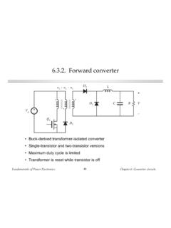
9 Vc n +. Exhibits a boost-type conversion characteristic fundamentals of power Electronics 23 Chapter 6: Converter Circuits A short list of converters An infinite number of converters are possible, which contain switches embedded in a network of inductors and capacitors Two simple classes of converters are listed here: Single-input single-output converters containing a single inductor. The switching period is divided into two subintervals. This class contains eight converters. Single-input single-output converters containing two inductors. The switching period is divided into two subintervals. Several of the more interesting members of this class are listed. fundamentals of power Electronics 24 Chapter 6: Converter Circuits Single-input single-output converters containing one inductor Use switches to connect inductor between source and load, in one manner during first subinterval and in another during second subinterval There are a limited number of ways to do this, so all possible combinations can be found After elimination of degenerate and redundant cases, eight converters are found: dc-dc converters buck boost buck-boost noninverting buck-boost dc-ac converters bridge Watkins-Johnson ac-dc converters current-fed bridge inverse of Watkins-Johnson fundamentals of power Electronics 25 Chapter 6: Converter Circuits Converters producing a unipolar output voltage 1.
10 Buck M(D) = D. M(D). 1 1. +. 2. Vg + V . 0. 0 1 D. M(D) = 1 M(D). 2. Boost 1 D. 2 4. + 3. 1 2. Vg + V. 1. 0. 0 1 D. fundamentals of power Electronics 26 Chapter 6: Converter Circuits Converters producing a unipolar output voltage D 0 1 D. 3. Buck-boost M(D) = 0. 1 D. 1. 1 2 +. 2. Vg + V 3.. 4. M(D). 4. Noninverting buck-boost M(D) = D. 1 D M(D). 1 2 4. + 3. 2 1 2. Vg + V. 1. 0. 0 1 D. fundamentals of power Electronics 27 Chapter 6: Converter Circuits Converters producing a bipolar output voltage suitable as dc-ac inverters 5. Bridge M(D) = 2D 1. M(D). 1. 1 2. Vg +. + V 0. 2 1 1 D. 1. 6. Watkins-Johnson M(D) = 2D 1 M(D). D. 1 1. 2 1. + or + 0. 1. 1 D. Vg + V Vg + V. 2 2. 3. 1 2 . fundamentals of power Electronics 28 Chapter 6: Converter Circuits Converters producing a bipolar output voltage suitable as ac-dc rectifiers M(D).