Transcription of Fundamentals of Power Electronics - University of Colorado ...
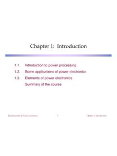
1 Fundamentals of Power ElectronicsChapter 1: Introduction1 Fundamentals of Power ElectronicsSecond editionRobert W. EricksonDragan MaksimovicUniversity of Colorado , BoulderFundamentals of Power ElectronicsChapter 1: Introduction2 Chapter 1: Introduction to Power Some applications of Power Elements of Power electronicsSummary of the courseFundamentals of Power ElectronicsChapter 1: Introduction to Power ProcessingDc-dc conversion:Change and control voltage magnitudeAc-dc rectification:Possibly control dc voltage, ac currentDc-ac inversion:Produce sinusoid of controllablemagnitude and frequencyAc-ac cycloconversion.
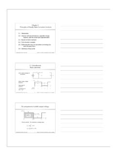
2 Change and control voltage magnitudeand frequencySwitchingconverterPowerinputPow eroutputControlinputFundamentals of Power ElectronicsChapter 1: Introduction4 Control is invariably requiredSwitchingconverterPowerinputPowe routputControlinputControllerreferencefe edbackfeedforwardFundamentals of Power ElectronicsChapter 1: Introduction5 High efficiency is essentialHigh efficiency leads to lowpower loss within converterSmall size and reliable operationis then feasibleEfficiency is a good measure ofconverter / Pout =PoutPinPloss=Pin Pout=Pout1 1 Fundamentals of Power ElectronicsChapter 1: Introduction6A high-efficiency converterA goal of current converter technology is to construct converters of smallsize and weight, which process substantial Power at high efficiencyConverterPinPoutFundamentals of Power ElectronicsChapter 1: Introduction7 Devices available to the circuit designerDTsTsResistorsCapacitorsMagnetic sSemiconductor devicesLinear-mode+ Switched-modeFundamentals of Power ElectronicsChapter 1: Introduction8 Devices available to the circuit designerSignal processing.
3 Avoid magneticsDTsTsResistorsCapacitorsMagneti csSemiconductor devicesLinear-mode+ Switched-modeFundamentals of Power ElectronicsChapter 1: Introduction9 Devices available to the circuit designerPower processing: avoid lossy elementsDTsTsResistorsCapacitorsMagnetic sSemiconductor devicesLinear-mode+ Switched-modeFundamentals of Power ElectronicsChapter 1: Introduction10 Power loss in an ideal switchSwitch closed:v(t) = 0 Switch open:i(t) = 0In either event:p(t) = v(t) i(t) = 0 Ideal switch consumes zero Power +v(t) i(t) Fundamentals of Power ElectronicsChapter 1: Introduction11A simple dc-dc converter exampleInput source: 100 VOutput load: 50V, 10A, 500 WHow can this converter be realized?
4 + R5 +V50V Vg100VI10 ADc-dcconverterFundamentals of Power ElectronicsChapter 1: Introduction12 Dissipative realizationResistive voltage divider+ R5 +V50V Vg100VI10A+ 50V Ploss = 500 WPout = 500 WPin = 1000 WFundamentals of Power ElectronicsChapter 1: Introduction13 Dissipative realizationSeries pass regulator: transistor operates inactive region+ R5 +V50V Vg100VI10A+ 50V Ploss 500 WPout = 500 WPin 1000W+ linear amplifierand base driverVrefFundamentals of Power ElectronicsChapter 1: Introduction14 Use of a SPDT switch+ R+v(t)50 V 12+vs(t) Vg100 VI10 Avs(t)VgDTs(1 D) Ts0tswitchposition:121Vs = DVgFundamentals of Power ElectronicsChapter 1: Introduction15 The switch changes the dc voltage levelD = switch duty cycle0 D 1Ts = switching periodfs = switching frequency = 1 / TsVs=1 Tsvs(t)dt0Ts=DVgDC component of vs(t) = average value:vs(t)VgDTs(1 D) Ts0tswitchposition:121Vs = DVgFundamentals of Power ElectronicsChapter 1: Introduction16 Addition of low pass filterAddition of (ideally lossless) L-C low-pass filter, forremoval of switching harmonics.
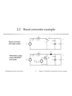
5 Choose filter cutoff frequency f0 much smaller than switchingfrequency fs This circuit is known as the buck converter + R+v(t) 12+vs(t) Vg100 Vi(t)LCPloss smallPout = 500 WPin 500 WFundamentals of Power ElectronicsChapter 1: Introduction17 Addition of control systemfor regulation of output voltage (t)TsdTst+ +v vgSwitching converterPowerinputLoad +CompensatorvrefReferenceinputHvPulse-wi dthmodulatorvcTransistorgate driver Gc(s)H(s)veErrorsignalSensorgainiFundame ntals of Power ElectronicsChapter 1: Introduction18 The boost converter+ LCR+V of Power ElectronicsChapter 1: Introduction19A single-phase inverter12+ load+ v(t) 21 Vgvs(t)+ tvs(t) H-bridge Modulate switchduty cycles toobtain sinusoidallow-frequencycomponentFundamen tals of Power ElectronicsChapter 1: Several applications of Power electronicsPower levels encountered in high-efficiency converters less than 1 W in battery-operated portable equipment tens, hundreds, or thousands of watts in Power supplies forcomputers or office equipment kW to MW in variable-speed motor drives 1000 MW in rectifiers and inverters for utility dc transmissionlinesFundamentals of Power ElectronicsChapter 1.
6 Introduction21A laptop computer Power supply systemvac(t)iac(t)ChargerPWMR ectifierLithiumbatteryac line input85 265 VrmsInverterBuckconverterBoostconverterD isplaybacklightingMicroprocessorPowerman agementDiskdriveFundamentals of Power ElectronicsChapter 1: Introduction22 Power system of an earth-orbiting spacecraftSolararray+vbus BatteriesBatterycharge/dischargecontroll ersDc-dcconverterPayloadDc-dcconverterPa yloadDissipativeshunt regulatorFundamentals of Power ElectronicsChapter 1: Introduction23An electric vehicle Power and drive system3 ac line50/60 HzBatterychargerbattery+vb Variable-frequencyVariable-voltage acInverterac machineInverterInverterac machineDC-DCconverter PsystemcontrollerVehicleelectronicsLow-v oltagedc buscontrol busac machineac machineInverterFundamentals of Power ElectronicsChapter 1: Elements of Power electronicsPower Electronics incorporates concepts from the fields ofanalog circuitselectronic devicescontrol systemspower systemsmagneticselectric machinesnumerical simulationFundamentals of Power ElectronicsChapter 1: Introduction25 Part I.
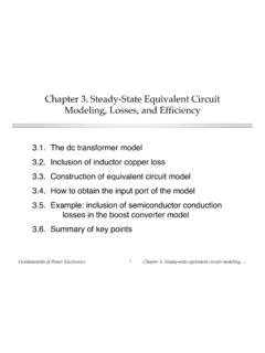
7 Converters in equilibriumiL(t)t0 DTsTsIiL(0)Vg VLiL(DTs) iL VLvL(t)Vg Vt VD'TsDTsswitchposition:121RL+ VgD' RD+ D' VDD RonR+V ID' : 1 Inductor waveformsAveraged equivalent circuitD RL/R = efficiencyDiscontinuous conduction modeTransformer isolationFundamentals of Power ElectronicsChapter 1: Introduction26 Switch realization: semiconductor devicesCollectorpn-nnppEmitterGatennmino rity carrierinjectioncollectoremittergateThe IGBTtiL Vg0iB(t)vB(t)area Qr0trtiLVg0iA(t)vA(t)Qr0tarea~QrVgarea~i LVgtrt0t1t2transistorwaveformsdiodewavef ormspA(t)= vA iASwitching lossFundamentals of Power ElectronicsChapter 1: Introduction27 Part I.
8 Converters in equilibrium2. Principles of steady state converter analysis3. Steady-state equivalent circuit modeling, losses, and efficiency4. Switch realization5. The discontinuous conduction mode6. Converter circuitsFundamentals of Power ElectronicsChapter 1: Introduction28 Part II. Converter dynamics and control+ +v(t) vg(t)Switching converterPowerinputLoad +RcompensatorGc(s)vrefvoltagereferencevf eedbackconnectionpulse-widthmodulatorvct ransistorgate driver (t) (t)TsdTsttvc(t)Controllerttgatedriveactu al waveform v(t)including rippleaveraged waveform <v(t)>Tswith ripple neglected+ Id(t)vg(t)+ LVg Vd(t)+v(t) RCId(t)1 : DD' : 1 Closed-loop converter systemAveraging the waveformsSmall-signalaveragedequivalent circuitFundamentals of Power ElectronicsChapter 1: Introduction29 Part II.
9 Converter dynamics and control7. Ac modeling8. Converter transfer functions9. Controller design10. Input filter design11. Ac and dc equivalent circuit modeling of the discontinuousconduction mode12. Current-programmed controlFundamentals of Power ElectronicsChapter 1: Introduction30 Part III. Magnetics i i3i 2i2i2 frequencyBmax (T)25kHz50kHz100kHz200kHz250kHz400kHz500 kHz1000kHzPot core size42263622261622131811181122132616n1 : n2: nkR1R2 Rki1(t)i2(t)ik(t)LMiM(t)transformerdesig ntransformersize of Power ElectronicsChapter 1: Introduction31 Part III. Magnetics13. Basic magnetics theory14. Inductor design15.
10 Transformer designFundamentals of Power ElectronicsChapter 1: Introduction32 Part IV. Modern rectifiers,and Power system harmonics100%91%73%52%32%19%15% 15%13%9%0%20%40%60%80%100%13579111315171 9 Harmonic numberHarmonic amplitude,percent of fundamentalTHD = 136%Distortion factor = 59%Pollution of Power system byrectifier current harmonicsRe(vcontrol)+ vac(t)iac(t)vcontrolv(t)i(t)+ p(t) = vac2 / ReIdeal rectifier (LFR)acinputdcoutputboost convertercontrollerRvac(t)iac(t)+vg(t) ig(t)ig(t)vg(t)+v(t) i(t)Q1 LCD1vcontrol(t)multiplierX+ vref(t)= kx vg(t) vcontrol(t)Rsva(t)Gc(s)PWMcompensatorver r(t)A low-harmonic rectifier systemModel ofthe idealrectifierFundamentals of Power ElectronicsChapter 1: Introduction33 Part IV.