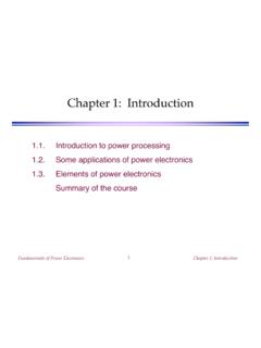
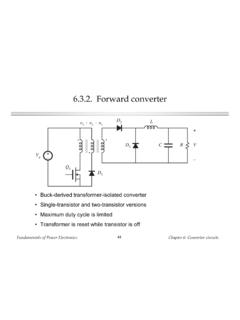
Transcription of 2.1 Introduction Buck converter
1 fundamentals of power ElectronicsChapter 2: Principles of steady-state converter analysis1 Chapter 2 Principles of Steady-State converter volt-second balance, capacitor chargebalance, and the small ripple Boost converter Cuk converter the ripple in converters containing two-pole low-pass of key pointsFundamentals of power ElectronicsChapter 2: Principles of steady-state converter IntroductionBuck converterSPDT switch changes dccomponentSwitch output voltagewaveformcomplement D :D = 1 - DDuty cycle D:0 D 1+ R+v(t) 12+vs(t) Vgvs(t)VgDTsD'Ts0t0 DTsTsSwitchposition:121 fundamentals of power ElectronicsChapter 2: Principles of steady-state converter analysis3Dc component of switch output voltagevs=1 Tsvs(t)dt0 Tsvs=1Ts(DTsVg)=DVgFourier analysis: Dc component = average valuevs(t)Vg0t0 DTsTs vs = DVgarea =DTsVgFundamentals of power ElectronicsChapter 2: Principles of steady-state converter analysis4 Insertion of low-pass filter to remove switchingharmonics and pass only dc componentv vs=DVg+ LCR+v(t) 12+vs(t) VgVg00DV1 fundamentals of power ElectronicsChapter 2: Principles of steady-state converter analysis5 Three basic dc-dc convertersBuckBoostBuck-boostM(D) (D) (D)D 5 4 3 2 (a)(b)(c)+ LCR+v 12+ LCR+v 12+ LCR+v 12M(D)=DM(D)=11 DM(D)= D1 DiL(t)VgiL(t)VgiL(t)VgFundamentals of power ElectronicsChapter 2.
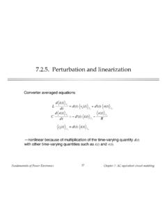
2 Principles of steady-state converter analysis6 Objectives of this chapter Develop techniques for easily determining outputvoltage of an arbitrary converter circuit Derive the principles of inductor volt-second balanceand capacitor charge (amp-second) balance Introduce the key small ripple approximation Develop simple methods for selecting filter elementvalues Illustrate via examplesFundamentals of power ElectronicsChapter 2: Principles of steady-state converter Inductor volt-second balance, capacitor chargebalance, and the small ripple approximationBuck convertercontaining practicallow-pass filterActual output voltagewaveformv(t)=V+vripple(t)Actual output voltage waveform, buck converter + LCR+v(t) 12iL(t)+ vL(t) iC(t)Vgv(t)t0 VActual waveformv(t) = V + vripple(t)dc component VFundamentals of power ElectronicsChapter 2: Principles of steady-state converter analysis8 The small ripple approximationIn a well-designed converter , the output voltage ripple is small.
3 Hence,the waveforms can be easily determined by ignoring the ripple:v(t) Vv(t)=V+vripple(t)v(t)t0 VActual waveformv(t) = V + vripple(t)dc component Vvripple<VFundamentals of power ElectronicsChapter 2: Principles of steady-state converter analysis9 Buck converter analysis:inductor current waveformoriginalconverterswitch in position 2switch in position 1+ LCR+v(t) 12iL(t)+ vL(t) iC(t)VgLCR+v(t) iL(t)+ vL(t) iC(t)+ VgLCR+v(t) iL(t)+ vL(t) iC(t)+ VgFundamentals of power ElectronicsChapter 2: Principles of steady-state converter analysis10 Inductor voltage and currentSubinterval 1: switch in position 1vL=Vg v(t)Inductor voltageSmall ripple approximation:vL Vg VKnowing the inductor voltage, we can now find the inductor current viavL(t)=LdiL(t)dtSolve for the slope:diL(t)dt=vL(t)L Vg VL The inductor current changes with anessentially constant slopeLCR+v(t) iL(t)+ vL(t) iC(t)+ VgFundamentals of power ElectronicsChapter 2: Principles of steady-state converter analysis11 Inductor voltage and currentSubinterval 2: switch in position 2 Inductor voltageSmall ripple approximation:Knowing the inductor voltage, we can again find the inductor current viavL(t)=LdiL(t)dtSolve for the slope: The inductor current changes with anessentially constant slopevL(t)= v(t)vL(t) VdiL(t)dt VLLCR+v(t) iL(t)+ vL(t) iC(t)+ VgFundamentals of power ElectronicsChapter 2: Principles of steady-state converter analysis12 Inductor voltage and current waveformsvL(t)=LdiL(t)dtvL(t)Vg Vt VD'TsDTsSwitchposition.
4 121 VLVg VLiL(t)t0 DTsTsIiL(0)iL(DTs) iLFundamentals of power ElectronicsChapter 2: Principles of steady-state converter analysis13 Determination of inductor current ripple magnitude(change in iL)=(slope)(length of subinterval)2 iL=Vg VLDTs iL=Vg V2 LDTsL=Vg V2 iLDTs VLVg VLiL(t)t0 DTsTsIiL(0)iL(DTs) iLFundamentals of power ElectronicsChapter 2: Principles of steady-state converter analysis14 Inductor current waveformduring turn-on transientWhen the converter operates in equilibrium:iL((n+1)Ts)=iL(nTs)iL(t)t0 DTsTsiL(0) = 0iL(nTs)iL(Ts)2 TsnTs(n + 1)TsiL((n + 1)Ts)Vg v(t)L v(t)LFundamentals of power ElectronicsChapter 2: Principles of steady-state converter analysis15 The principle of inductor volt-second balance:DerivationInductor defining relation:Integrate over one complete switching period:In periodic steady state, the net change in inductor current is zero:Hence, the total area (or volt-seconds) under the inductor voltagewaveform is zero whenever the converter operates in steady equivalent form:The average inductor voltage is zero in steady (t)=LdiL(t)dtiL(Ts) iL(0) =1 LvL(t)dt0Ts0=vL(t)dt0Ts0=1 TsvL(t)dt0Ts=vLFundamentals of power ElectronicsChapter 2: Principles of steady-state converter analysis16 Inductor volt-second balance:Buck converter exampleInductor voltage waveform,previously derived:Integral of voltage waveform is area of rectangles: =vL(t)dt0Ts=(Vg V)(DTs)+( V)(D'Ts)Average voltage isvL= Ts=D(Vg V)+D'( V)Equate to zero and solve for V.
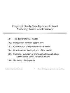
5 0=DVg (D+D')V=DVg V V=DVgvL(t)Vg Vt VDTsTotal area fundamentals of power ElectronicsChapter 2: Principles of steady-state converter analysis17 The principle of capacitor charge balance:DerivationCapacitor defining relation:Integrate over one complete switching period:In periodic steady state, the net change in capacitor voltage is zero:Hence, the total area (or charge) under the capacitor currentwaveform is zero whenever the converter operates in steady average capacitor current is then (t)=CdvC(t)dtvC(Ts) vC(0) =1 CiC(t)dt0Ts0=1 TsiC(t)dt0Ts=iCFundamentals of power ElectronicsChapter 2: Principles of steady-state converter Boost converter exampleBoost converterwith ideal switchRealization usingpower MOSFETand diode+ LCR+v 12iL(t)VgiC(t)+ vL(t) + LCR+v iL(t)VgiC(t)+ vL(t) D1Q1 DTsTs+ fundamentals of power ElectronicsChapter 2: Principles of steady-state converter analysis19 Boost converter analysisoriginalconverterswitch in position 2switch in position 1+ LCR+v 12iL(t)VgiC(t)+ vL(t) CR+v iC(t)+ LiL(t)Vg+ vL(t) CR+v iC(t)+ LiL(t)Vg+ vL(t) fundamentals of power ElectronicsChapter 2: Principles of steady-state converter analysis20 Subinterval 1: switch in position 1 Inductor voltage and capacitor currentSmall ripple approximation:vL=VgiC= v/RvL=VgiC= V/RCR+v iC(t)+ LiL(t)Vg+ vL(t) fundamentals of power ElectronicsChapter 2.
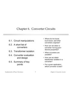
6 Principles of steady-state converter analysis21 Subinterval 2: switch in position 2 Inductor voltage and capacitor currentSmall ripple approximation:vL=Vg viC=iL v/RvL=Vg ViC=I V/RCR+v iC(t)+ LiL(t)Vg+ vL(t) fundamentals of power ElectronicsChapter 2: Principles of steady-state converter analysis22 Inductor voltage and capacitor current waveformsvL(t)Vg VtDTsVgD'TsiC(t) V/RtDTsI V/RD'TsFundamentals of power ElectronicsChapter 2: Principles of steady-state converter analysis23 Inductor volt-second balanceNet volt-seconds applied to inductorover one switching period:vL(t)dt0Ts=(Vg)DTs+(Vg V)D'TsEquate to zero and collect terms:Vg(D+D') VD'=0 Solve for V:V=VgD'The voltage conversion ratio is thereforeM(D)=VVg=1D'=11 DvL(t)Vg VtDTsVgD'TsFundamentals of power ElectronicsChapter 2: Principles of steady-state converter analysis24 Conversion ratio M(D) of the boost converterM(D) (D)=1D'=11 DFundamentals of power ElectronicsChapter 2: Principles of steady-state converter analysis25 Determination of inductor current dc componentCapacitor charge balance:iC(t)dt0Ts=( VR)DTs+(I VR)D'TsCollect terms and equate to zero: VR(D+D') +ID'=0 Solve for I:I=VD'RI=VgD'2 REliminate V to express in terms of Vg:iC(t) V/RtDTsI V/RD' of power ElectronicsChapter 2: Principles of steady-state converter analysis26 Determination of inductor current rippleInductor current slope duringsubinterval 1.
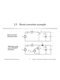
7 DiL(t)dt=vL(t)L=Vg VLInductor current slope duringsubinterval 2:2 iL=VgLDTsdiL(t)dt=vL(t)L=VgLChange in inductor current during subinterval 1 is (slope) (length of subinterval):Solve for peak ripple: iL=Vg2 LDTs Choose L such that desired ripple magnitudeis obtainedVg VLVgLiL(t)t0 DTsTsI iLFundamentals of power ElectronicsChapter 2: Principles of steady-state converter analysis27 Determination of capacitor voltage rippleCapacitor voltage slope duringsubinterval 1:Capacitor voltage slope duringsubinterval 2:Change in capacitor voltage during subinterval 1 is (slope) (length of subinterval):Solve for peak ripple: Choose C such that desired voltage ripplemagnitude is obtained In practice, capacitor equivalent seriesresistance (esr) leads to increased voltage rippledvC(t)dt=iC(t)C= VRCdvC(t)dt=iC(t)C=IC VRC 2 v= VRCDTs v=V2 RCDTsv(t)t0 DTsTsV vIC VRC VRCF undamentals of power ElectronicsChapter 2: Principles of steady-state converter Cuk converter example+ L1C2R+v2 C1L212+ v1 i1i2Vg+ L1C2R+v2 C1L2+ v1 i1i2D1Q1 VgCuk converter ,with ideal switchCuk converter :practical realizationusing MOSFET anddiodeFundamentals of power ElectronicsChapter 2: Principles of steady-state converter analysis29 Cuk converter circuitwith switch in positions 1 and 2+ L1C2R+v2 C1L2i1i2 v1+iC1iC2+ vL2 + vL1 Vg+ L1C2R+v2 C1L2i1i2 + v1 iC1iC2+ vL2 + vL1 VgSwitch in position 1.
8 MOSFET conductsCapacitor C1 releasesenergy to outputSwitch in position 2:diode conductsCapacitor C1 ischarged from inputFundamentals of power ElectronicsChapter 2: Principles of steady-state converter analysis30 Waveforms during subinterval 1 MOSFET conduction interval+ L1C2R+v2 C1L2i1i2 v1+iC1iC2+ vL2 + vL1 VgvL1=VgvL2= v1 v2iC1=i2iC2=i2 v2 RInductor voltages andcapacitor currents:Small ripple approximation for subinterval 1:vL1=VgvL2= V1 V2iC1=I2iC2=I2 V2 RFundamentals of power ElectronicsChapter 2: Principles of steady-state converter analysis31 Waveforms during subinterval 2 Diode conduction intervalInductor voltages andcapacitor currents:Small ripple approximation for subinterval 2:+ L1C2R+v2 C1L2i1i2 + v1 iC1iC2+ vL2 + vL1 VgvL1=Vg v1vL2= v2iC1=i1iC2=i2 v2 RvL1=Vg V1vL2= V2iC1=I1iC2=I2 V2 RFundamentals of power ElectronicsChapter 2: Principles of steady-state converter analysis32 Equate average values to zeroThe principles of inductor volt-second and capacitor charge balancestate that the average values of the periodic inductor voltage andcapacitor current waveforms are zero, when the converter operates insteady state.
9 Hence, to determine the steady-state conditions in theconverter, let us sketch the inductor voltage and capacitor currentwaveforms, and equate their average values to :vL1(t)Vg V1tDTsVgD'TsInductor voltage vL1(t)vL1=DVg+D'(Vg V1)=0 Volt-second balance on L1: fundamentals of power ElectronicsChapter 2: Principles of steady-state converter analysis33 Equate average values to zerovL2(t) V1 V2tDTs V2D'TsiC1(t)I2tDTsI1D'TsInductor L2 voltageCapacitor C1 currentvL2=D( V1 V2)+D'( V2)=0iC1=DI2+D'I1=0 Average the waveforms: fundamentals of power ElectronicsChapter 2: Principles of steady-state converter analysis34 Equate average values to zeroiC2(t)I2 V2 / R (= 0)tDTsD'TsCapacitor current iC2(t) waveformNote: during both subintervals, thecapacitor current iC2 is equal to thedifference between the inductor currenti2 and the load current V2/R.
10 Whenripple is neglected, iC2 is constant andequal to V2R=0 fundamentals of power ElectronicsChapter 2: Principles of steady-state converter analysis35 Cuk converter conversion ratio M = V/VgM(D) (D)=V2Vg= D1 DFundamentals of power ElectronicsChapter 2: Principles of steady-state converter analysis36 Inductor current waveformsdi1(t)dt=vL1(t)L1=VgL1di2(t)dt= vL2(t)L2= V1 V2L2 Interval 1 slo