Transcription of Chapter 4. Switch Realization - University of Colorado Boulder
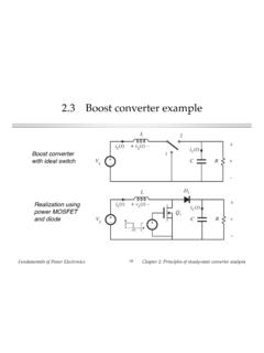
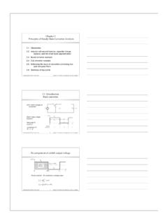
1 fundamentals of power ElectronicsChapter 4: Switch realization1 Chapter 4. Switch Switch applicationsSingle-, two-, and four-quadrant switches. Synchronous A brief survey of power semiconductor devicesPower diodes, MOSFETs, BJTs, IGBTs, and Switching lossTransistor switching with clamped inductive load. Dioderecovered charge. Stray capacitances and inductances, andringing. Efficiency vs. switching Summary of key pointsFundamentals of power ElectronicsChapter 4: Switch realization2 SPST (single-pole single-throw) switchesSPST Switch , withvoltage and currentpolarities definedBuck converterwith SPDT Switch :with two SPST switches:All power semiconductordevices function as + 10 LCR+V iL(t)+ 12 VgLCR+V iL(t)+ + vA vB+ABiAiBVgFundamentals of power ElectronicsChapter 4: Switch realization3 Realization of SPDT Switch using two SPST switches A nontrivial step: two SPST switches are not exactly equivalent to oneSPDT Switch It is possible for both SPST switches to be simultaneously ON or OFF Behavior of converter is then significantly modified discontinuous conduction modes ( Chapter 5) Conducting state of SPST Switch may depend on applied voltage orcurrent for example: diodeFundamentals of power ElectronicsChapter 4: Switch realization4 Quadrants of SPST Switch operationA single-quadrantswitch example:ON-state: i > 0 OFF-state.
2 V > 0iv+ 10 Switchoff state voltageSwitchon statecurrentFundamentals of power ElectronicsChapter 4: Switch realization5 Some basic Switch applicationsswitchoff-state voltageswitchon-statecurrentswitchon-sta tecurrentswitchoff-statevoltageswitchon- statecurrentswitchoff-statevoltageswitch on-statecurrentswitchoff-statevoltageSin gle-quadrantswitchCurrent-bidirectionalt wo-quadrantswitchVoltage-bidirectionaltw o-quadrantswitchFour-quadrantswitchFunda mentals of power ElectronicsChapter 4: Switch Single-quadrant switchesActive Switch : Switch state is controlled exclusivelyby a third terminal (control terminal).Passive Switch : Switch state is controlled by theapplied current and/or voltage at terminals 1 and : A special case turn-on transition is active,while turn-off transition is Switch : on-state i(t) and off-state v(t)are + 10 fundamentals of power ElectronicsChapter 4: Switch realization7 The diodeSymbolinstantaneous i-v characteristic A passive Switch Single-quadrant Switch : can conduct positive on-state current can block negative off-state voltage provided that the intendedon-state and off-stateoperating points lie on thediode i-v characteristic,then Switch can berealized using a diodei10v+ ivonoffFundamentals of power ElectronicsChapter 4: Switch realization8 The Bipolar Junction Transistor (BJT) and theInsulated Gate Bipolar Transistor (IGBT)BJTIGBT instantaneous i-v characteristic An active Switch , controlledby terminal C Single-quadrant Switch .
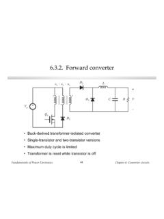
3 Can conduct positive on-state current can block positive off-statevoltage provided that the intendedon-state and off-stateoperating points lie on thetransistor i-v characteristic,then Switch can be realizedusing a BJT or IGBT ivonoffi10v+ Ci10v+ CFundamentals of power ElectronicsChapter 4: Switch realization9 The Metal-Oxide Semiconductor Field EffectTransistor (MOSFET)Symbolinstantaneous i-v characteristic An active Switch , controlled byterminal C Normally operated as single-quadrant Switch : can conduct positive on-statecurrent (can also conductnegative current in somecircumstances) can block positive off-statevoltage provided that the intended on-state and off-state operatingpoints lie on the MOSFET i-vcharacteristic, then Switch canbe realized using a MOSFET ivonoffon(reverse conduction)i10v+ CFundamentals of power ElectronicsChapter 4: Switch realization10 Realization of Switch using transistors and diodesBuck converter exampleSPST switchoperating pointsSwitch ASwitch BSwitch A: transistorSwitch B: diodeiAvAiLVgSwitch AonSwitch AoffiBvBiL VgSwitch BonSwitch BoffLCR+V iL(t)+ + vA vB+ABiAiBVgFundamentals of power ElectronicsChapter 4: Switch realization11 Realization of buck converterusing single-quadrant switches+ LiL(t)iAvAvB+ iBvL(t)+ + VgiAvAiLVgSwitch AonSwitch AoffiBvBiL VgSwitch BonSwitch BoffFundamentals of power ElectronicsChapter 4: Switch Current-bidirectionaltwo-quadrant switchesi10v+ Civon(transistor conducts)offon(diode conducts)BJT / anti-paralleldiode realizationinstantaneous i-vcharacteristic Usually an active Switch ,controlled by terminal C Normally operated as two-quadrant Switch .
4 Can conduct positive ornegative on-state current can block positive off-statevoltage provided that the intended on-state and off-state operatingpoints lie on the composite i-vcharacteristic, then Switch canbe realized as shownFundamentals of power ElectronicsChapter 4: Switch realization13 Two quadrant switchesswitchon-statecurrentswitchoff-s tatevoltageivon(transistor conducts)offon(diode conducts)iv+ 10 fundamentals of power ElectronicsChapter 4: Switch realization14 MOSFET body diodei10v+ Civon(transistor conducts)offon(diode conducts) power MOSFET,and its integralbody diodeUse of external diodesto prevent conductionof body diodePower MOSFET characteristicsFundamentals of power ElectronicsChapter 4: Switch realization15A simple inverter+ L+ VgVgCRQ1Q2D1D2iLiAiBv0+ vB+ vA+ v0(t)=(2D 1)VgFundamentals of power ElectronicsChapter 4: Switch realization16 Inverter: sinusoidal modulation of Dv0(t)=(2D 1)VgD(t)= +Dmsin ( t)v0 DVg modulation toproduce ac output:iL(t)=v0(t)R=(2D 1)VgRThe resulting inductorcurrent variation is alsosinusoidal:Hence, current-bidirectionaltwo-quadrant switches of power ElectronicsChapter 4: Switch realization17 The dc-3 ac voltage source inverter (VSI)+ VgiaibicSwitches must block dc input voltage, and conduct ac load of power ElectronicsChapter 4: Switch realization18 Bidirectional battery charger/dischargerLQ1Q2D1D2vbatt+ vbusspacecraftmain power bus+ vbus > vbattA dc-dc converter with bidirectional power of power ElectronicsChapter 4: Switch Voltage-bidirectional two-quadrant switchesBJT / seriesdiode realizationinstantaneous i-vcharacteristic Usually an active Switch ,controlled by terminal C Normally operated as two-quadrant Switch .
5 Can conduct positive on-statecurrent can block positive or negativeoff-state voltage provided that the intended on-state and off-state operatingpoints lie on the composite i-vcharacteristic, then Switch canbe realized as shown The SCR is such a device,without controlled turn-offi10v+ Civonoff(transistorblocks voltage)off(diodeblocks voltage) fundamentals of power ElectronicsChapter 4: Switch realization20 Two-quadrant switchesiv+ 10ivonoff(transistorblocks voltage)off(diodeblocks voltage)switchon-statecurrentswitchoff-s tatevoltagei10v+ CFundamentals of power ElectronicsChapter 4: Switch realization21A dc-3 ac buck-boost inverter+ iLVg a b c+vab(t) +vbc(t) Requires voltage-bidirectional two-quadrant example: boost-type inverter, or current-source inverter (CSI). fundamentals of power ElectronicsChapter 4: Switch Four-quadrant switchesswitchon-statecurrentswitchoff-s tatevoltage Usually an active Switch ,controlled by terminal C can conduct positive ornegative on-state current can block positive or negativeoff-state voltageFundamentals of power ElectronicsChapter 4: Switch realization23 Three ways to realize a four-quadrant switchi10v+ i10v+ i10v+ iv+ 10 fundamentals of power ElectronicsChapter 4: Switch realization24A 3 ac-3 ac matrix converteribicia+ + + van(t)vcn(t)vbn(t)3 ac input3 ac output All voltages and currents are ac; hence, four-quadrant switches are required.
6 Requires nine four-quadrant switchesFundamentals of power ElectronicsChapter 4: Switch Synchronous rectifiersiv+ 10i10v+ Civonoffon(reverse conduction)Replacement of diode with a backwards-connected MOSFET,to obtain reduced conduction lossi10v+ ideal Switch conventionaldiode rectifierMOSFET assynchronousrectifierinstantaneous i-vcharacteristicFundamentals of power ElectronicsChapter 4: Switch realization26 Buck converter with synchronous rectifier+ VgLiL(t)iAvAvB+ iB+ Q1Q2CC MOSFET Q2 iscontrolled to turn onwhen diode wouldnormally conduct Semiconductorconduction loss canbe made arbitrarilysmall, by reductionof MOSFET on-resistances Useful in low-voltagehigh-currentapplicationsFunda mentals of power ElectronicsChapter 4: Switch A brief survey of power semiconductor devices power diodes power MOSFETs Bipolar Junction Transistors (BJTs) Insulated Gate Bipolar Transistors (IGBTs) Thyristors (SCR, GTO, MCT) On resistance vs. breakdown voltage vs.
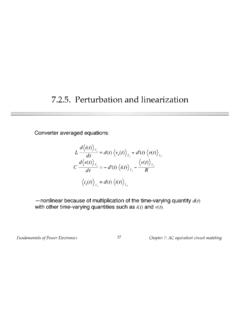
7 Switching times Minority carrier and majority carrier devicesFundamentals of power ElectronicsChapter 4: Switch Transistor switching with clamped inductive load+ LiL(t)iAvAvB+ iB+ DTsTs+ idealdiodephysicalMOSFET gatedriverVgtransistorwaveformsdiodewave formstttpA(t)= vA iAiLVgvA(t)iA(t)00iB(t)vB(t)00iL VgareaWoffVg iLt0t1t2 Buck converter exampletransistor turn-offtransitionWoff=12 VgiL(t2 t0)vB(t)=vA(t) VgiA(t)+iB(t)=iLFundamentals of power ElectronicsChapter 4: Switch realization29 Switching loss induced by transistor turn-off transitionWoff=12 VgiL(t2 t0)Psw=1 TspA(t)dtswitchingtransitions=(Won+Woff) fsEnergy lost during transistor turn-off transition:Similar result during transistor turn-on power loss: fundamentals of power ElectronicsChapter 4: Switch power diodesA power diode, under reverse-biased conditions:low doping concentration{{pn-n+ depletion region, reverse-biased+++ v v +EFundamentals of power ElectronicsChapter 4: Switch realization31 Typical diode switching waveformsti(t)area Qr0v(t)tr(1)(2)(3)(4)(5)(6)tdidtFundamen tals of power ElectronicsChapter 4: Switch realization32 Forward-biased power diodeconductivity modulationpn-n+ minority carrier injection+++ +++iv{ fundamentals of power ElectronicsChapter 4: Switch realization33 Charge-controlled behavior of the diodeTotal stored minority charge qpn-n+ +++iv}+++++q(t)=Q0e v(t) 1dq(t)dt=i(t) q(t) LThe diode equation:Charge control equation:With: = 1/(26 mV) at 300 K L = minority carrier lifetime(above equations don tinclude current thatcharges depletion regioncapacitance)In equilibrium: dq/dt = 0, and hencei(t)=q(t) L=Q0 Le v(t) 1=I0e v(t) 1 fundamentals of power ElectronicsChapter 4: Switch realization34 Charge-control in the diode.}}
8 Discussion The familiar i v curve of the diode is an equilibriumrelationship that can be violated during transientconditions During the turn-on and turn-off switching transients,the current deviates substantially from the equilibriumi v curve, because of change in the stored chargeand change in the charge within the reverse-biasdepletion region Under forward-biased conditions, the stored minoritycharge causes conductivity modulation of theresistance of the lightly-doped n region, reducing thedevice on-resistanceFundamentals of power ElectronicsChapter 4: Switch realization35 Diode in OFF state:reversed-biased, blocking voltageti(t)0v(t)(1)t{pn n+ Depletion region, reverse-biasedv v +E Diode is reverse-biased No stored minority charge: q = 0 Depletion region blocks appliedreverse voltage; charge is stored incapacitance of depletion regionFundamentals of power ElectronicsChapter 4: Switch realization36 Turn-on transientThe current i(t) isdetermined by theconverter circuit.}
9 Thiscurrent supplies: charge to increasevoltage acrossdepletion region charge needed tosupport the on-statecurrent charge to reduceon-resistance of n regionti(t)v(t)(1)(2)tCharge depletion regionDiode is forward-biased. Supply minoritycharge to n region to reduce on-resistanceDiode conducts with low on-resistanceOn-state current determined by converter circuitFundamentals of power ElectronicsChapter 4: Switch realization37 Turn-off transientRemoval of stored minority charge qpn-n+ +++i (< 0)v}+++++ fundamentals of power ElectronicsChapter 4: Switch realization38 Diode turn-off transientcontinuedti(t)Area Qr0v(t)tr(1)(2)(3)(4)(5)(6)tdidt(4) Diode remains stored charge in n region(5) Diode is depletion of power ElectronicsChapter 4: Switch realization39+ LiL(t)iAvAvB+ iB+ + silicondiodefasttransistorVgtiL Vg0iB(t)vB(t)area Qr0trtiLVg0iA(t)vA(t)Qr0tarea~QrVgarea~iLVgtrt0t1t2transistorwaveformsdiodewaveformspA(t)= vA iA Diode recovered stored chargeQr flows through transistorduring transistor turn-ontransition, inducing switchingloss Qr depends on diode on-stateforward current, and on therate-of-change of diode currentduring diode turn-off transitionThe diode switching transients induceswitching loss in the transistorsee Section of power ElectronicsChapter 4: Switch realization40 Switching loss calculationtiL Vg0iB(t)vB(t)area Qr0trtiLVg0iA(t)vA(t)Qr0tarea~QrVgarea~iLVgtrt0t1t2transistorwaveformsdiodewaveformspA(t)= vA iAWD=vA(t)iA(t)dtswitchingtransitionWD Vg(iL iB(t))dtswitchingtransition=VgiLtr+VgQrEnergy lost in transistor:With abrupt-recovery diode:Soft-recoverydiode:(t2 t1) >> (t1 t0)Abrupt-recoverydiode.
10 (t2 t1) << (t1 t0) Often, this is the largestcomponent of switching lossFundamentals of power ElectronicsChapter 4: Switch realization41 Types of power diodesStandard recoveryReverse recovery time not specified, intended for 50/60 HzFast recovery and ultra-fast recoveryReverse recovery time and recovered charge specifiedIntended for converter applicationsSchottky diodeA majority carrier deviceEssentially no recovered chargeModel with equilibrium i-v characteristic, in parallel withdepletion region capacitanceRestricted to low voltage (few devices can block 100V or more) fundamentals of power ElectronicsChapter 4: Switch realization42 Characteristics of several commercial powerrectifier diodesPart numberRated max voltage Rated avg currentVF (typical)tr (max)Fast recovery sUltra-fast recovery of power ElectronicsChapter 4: Switch realization43 Paralleling diodes+v1 +v2 i1i2iAttempts to parallel diodes, and share thecurrent so that i1 = i2 = i/2, generally don : thermal instability caused bytemperature dependence of the temperature leads to increasedcurrent, or reduced diode will hog the get the diodes to share the current, heroicmeasures are required: Select matched devices Package on common thermal substrate Build external circuitry that forces the currents to balanceFundamentals of power ElectronicsChapter 4: Switch realization44 Ringing induced by diode stored charge+ LiL(t)vL(t)+ + sili