Chapter 1: Introduction
Fundamentals of Power Electronics Chapter 1: Introduction2 Chapter 1: Introduction 1.1. Introduction to power processing 1.2. Some applications of power electronics 1.3. Elements of power electronics ... Fundamentals of Power Electronics Chapter 1: Introduction20 1.2 Several applications of power electronics
Download Chapter 1: Introduction

Information
Domain:
Source:
Link to this page:
Documents from same domain
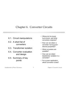
Chapter 6. Converter Circuits
eas.uccs.eduFundamentals of Power Electronics Chapter 6: Converter circuits1 Chapter 6. Converter Circuits 6.1. Circuit manipulations 6.2. A short list of converters
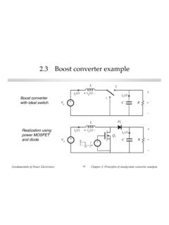
2.3 Boost converter example - University of Colorado ...
eas.uccs.eduFundamentals of Power Electronics Chapter 2: Principles of steady-state converter analysis18 2.3 Boost converter example Boost converter with ideal switch
Chapter 3. Steady-State Equivalent Circuit Modeling ...
eas.uccs.eduFundamentals of Power Electronics Chapter 3: ... Chapter 3. Steady-State Equivalent Circuit Modeling, Losses, and Efficiency 3.1. The dc transformer model 3.2. Inclusion of inductor copper loss ... conduction losses in the boost converter model 3.6. Summary of key points. Fundamentals of Power Electronics Chapter 3: Steady-state equivalent ...
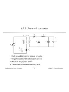
6.3.2. Forward converter - University of Colorado Colorado ...
eas.uccs.eduFundamentals of Power Electronics Chapter 6: Converter circuits54 Maximum duty cycle vs. transistor voltage stress Maximum duty cycle limited to which can be increased by increasing the turns ratio n2 / n1. But this increases the peak transistor voltage: For n1 …
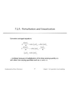
7.2.5. Perturbation and linearization
eas.uccs.eduFundamentals of Power Electronics! 29! Chapter 7: AC equivalent circuit modeling! Perturbation! So let us assume that the input voltage and duty cycle are equal to

4.2.1. Power diodes - University of Colorado Colorado Springs
eas.uccs.edusee Section 4.3.3! Fundamentals of Power Electronics! 22! Chapter 4: Switch realization! Energy associated with ringing! t –V 2 area – Q r t V 1 0 v i (t) t 1 t 2 t 3 v B (t) i L (t)
Related documents

SECTION 22 POWER ELECTRONICS - books.mhprofessional.com
books.mhprofessional.comPower electronics is an enabling technology that achieves conversion of electric power from one form to another, using a combination of high-power semiconductor devices and passive components— chiefly
Chapter 6. Converter Circuits
eas.uccs.eduFundamentals of Power Electronics Chapter 6: Converter circuits1 Chapter 6. Converter Circuits 6.1. Circuit manipulations 6.2. A short list of converters
2.3 Boost converter example - University of Colorado ...
eas.uccs.eduFundamentals of Power Electronics Chapter 2: Principles of steady-state converter analysis18 2.3 Boost converter example Boost converter with ideal switch
Chapter 3. Steady-State Equivalent Circuit Modeling ...
eas.uccs.eduFundamentals of Power Electronics Chapter 3: ... Chapter 3. Steady-State Equivalent Circuit Modeling, Losses, and Efficiency 3.1. The dc transformer model 3.2. Inclusion of inductor copper loss ... conduction losses in the boost converter model 3.6. Summary of key points. Fundamentals of Power Electronics Chapter 3: Steady-state equivalent ...
6.3.2. Forward converter - University of Colorado Colorado ...
eas.uccs.eduFundamentals of Power Electronics Chapter 6: Converter circuits54 Maximum duty cycle vs. transistor voltage stress Maximum duty cycle limited to which can be increased by increasing the turns ratio n2 / n1. But this increases the peak transistor voltage: For n1 …
7.2.5. Perturbation and linearization
eas.uccs.eduFundamentals of Power Electronics! 29! Chapter 7: AC equivalent circuit modeling! Perturbation! So let us assume that the input voltage and duty cycle are equal to
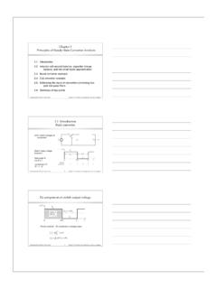
2.1 Introduction Buck converter
ece-www.colorado.eduFundamentals of Power Electronics Chapter 2: Principles of steady-state converter analysis1 Chapter 2 Principles of Steady-State Converter Analysis 2.1. Introduction 2.2. Inductor volt-second balance, capacitor charge balance, and the small ripple approximation 2.3. Boost converter example
Fundamentals of Power Electronics - University of Colorado ...
ecee.colorado.eduFundamentals of Power Electronics Chapter 1: Introduction20 1.2 Several applications of power electronics Power levels encountered in high-efficiency converters

Chapter 4. Switch Realization - University of Colorado Boulder
ecee.colorado.eduFundamentals of Power Electronics Chapter 4: Switch realization3 Realization of SPDT switch using two SPST switches A nontrivial step: two SPST switches are not exactly equivalent to one SPDT switch It is possible for both SPST switches to be simultaneously ON or OFF Behavior of converter is then significantly modified —discontinuous conduction modes (chapter 5)
Basic Electronics - NYU Tandon School of Engineering
engineering.nyu.eduBasic Electronics. Semiconductor ... •An AC2DC power supply is built using a transformer and a full-wave rectifier. •Transformer is used to step down the voltage i/p. •Rectifier converts AC to pulsed DC. •A filter capacitor is used to smooth out the pulses.
Related search queries
Power electronics, Power, Chapter 6. Converter Circuits, Fundamentals of Power Electronics, 2.3 Boost converter example, Steady-State Equivalent Circuit Modeling, Steady-State Equivalent Circuit Modeling, Losses, Perturbation and linearization, 2.1 Introduction, Of power electronics Power, Chapter 4. Switch Realization, Electronics