Transcription of Chapter 17 Table of Contents - Florida Department of ...
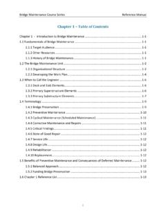
1 Bridge Maintenance Course Series Reference Manual i Chapter 17 Table of Contents Chapter 17 - Movable Bridges .. 17-1 Common Types of Movable Bridges .. 17-2 Terminology .. 17-2 Bascule Bridges .. 17-3 Vertical Lift Bridges .. 17-9 Swing Bridges .. 17-11 Operation of Movable Bridges .. 17-12 Counterweights .. 17-15 Mechanical Systems .. 17-17 Types of Span Drives .. 17-30 Open and Closed Gearing .. 17-34 Bearings .. 17-36 Electrical Systems .. 17-40 AC and DC Motors .. 17-48 Interlock 17-51 Preventive and Basic Maintenance of Movable Bridges .. 17-52 Open Gears .. 17-55 Closed Gearing (Speed Reducers) .. 17-57 Shafts and Couplings.
2 17-59 Bearings .. 17-59 Brakes .. 17-62 Air Buffers .. 17-63 Locks .. 17-63 Steel Counterweights and Auxiliary Counterweights .. 17-64 Live Load Bearings and Strike Plates .. 17-65 Wire Ropes .. 17-66 Counterweight Sheaves and Operating Drums .. 17-66 Span Guides .. 17-67 Tread Plates and Racks .. 17-67 Traffic Barriers .. 17-68 Electrical System .. 17-68 Bridge Maintenance Course Series Reference Manual ii Hydraulic System .. 17-72 Predictive 17-74 Structural Health Monitoring .. 17-75 Generator Maintenance .. 17-75 Lubrication of the Gears and Bearing Mechanisms .. 17-76 Types of Lubrication .. 17-77 Lubrication Conditions.
3 17-79 Selecting a Lubricant .. 17-79 Removing Grease .. 17-83 Lubricating Movable Bridge Components .. 17-84 Alignment .. 17-89 Repair of the Pivot/Rack Assembly .. 17-90 Balance Testing .. 17-91 Chapter 17 Reference List .. 17-93 Bridge Maintenance Course Series Reference Manual iii Chapter 17 List of Figures Figure Bicentennial Bascule Bridge over the St. Joseph River .. 17-1 Figure Single Leaf Simple Trunnion Bascule .. 17-5 Figure Cylinder Driven Simple Trunnion Bascule .. 17-6 Figure Types of Bascule Bridges (a) Simple Trunnion (b) Rolling Lift Bascule .. 17-7 Figure Rack and Pinion Gear .. 17-7 Figure Hydraulic Cylinder on Trunnion Bascule Bridge.
4 17-8 Figure Through Single-Leaf Scherzer Rolling Lift Bascule .. 17-9 Figure Span Driven Vertical Lift Bridge .. 17-9 Figure Tower Driven Vertical Lift Bridge .. 17-10 Figure Vertical Lift Bridge Schematic .. 17-10 Figure Center Bearing Swing Span Bridge .. 17-11 Figure Center-Bearing Swing Bridge Schematic .. 17-11 Figure Example of a Table of Contents of a Bridge Specific Movable Bridge .. 17-13 Figure Live Load Wedges and Shoes .. 17-14 Figure Components of a Span Drive .. 17-14 Figure Trunnion Bearing .. 17-15 Figure Counterweight Assembly .. 17-16 Figure Mechanical/Electrical System of Representative Movable Bridge .. 17-17 Figure Brake and Hydraulic Span Drive System.
5 17-17 Figure Open Gearing Operating 17-18 Figure Speed Reducer (Closed Gearing), Shaft, and Coupling .. 17-18 Figure Bearings Supporting Span Drive Shaft .. 17-19 Figure Typical Brake Assembly .. 17-20 Figure Air Buffer Schematic .. 17-21 Figure Air Buffers in the Retracted (left) and Not Retracted (right) Positions .. 17-21 Figure Mechanically Driven Span Lock .. 17-22 Figure Span Lock Bars and Shim Removal (Courtesy of UCF) .. 17-22 Figure Disengaged Span Lock (Courtesy of Indiana DOT) .. 17-23 Figure Engaged Tail Lock .. 17-23 Figure Tail Lock in Fully Engaged Position (left) and Disengaged Position (right) .. 17-24 Bridge Maintenance Course Series Reference Manual iv Figure Toe Lock on Double Bascule Bridge.
6 17-24 Figure Fixed Live Load Bearing .. 17-25 Figure Wire Rope Socket Terminations .. 17-25 Figure Operating Drum and Wire Rope with Rope Clip on Vertical Lift Bridge .. 17-26 Figure Counterweight Sheave .. 17-26 Figure Span Guide Rail Detail (Courtesy of Wisconsin DOT) .. 17-27 Figure Components of a Lifting Post (Courtesy of Wisconsin DOT) .. 17-28 Figure Moving Drum Equalizing System (Courtesy of Wisconsin DOT) .. 17-29 Figure Tread Plates .. 17-30 Figure Auxiliary Drive Assembly .. 17-31 Figure Type 1 Span Drive Schematic .. 17-32 Figure Type 2 Span Drive Schematic .. 17-33 Figure Type 3 Span Drive Schematic .. 17-34 Figure Open Gear.
7 17-35 Figure Rack and Pinion .. 17-35 Figure Closed Gear (Speed Reducer) .. 17-36 Figure Bearing .. 17-37 Figure Sleeve Bearing (Courtesy of NHDOT) .. 17-38 Figure Roller Bearing (Courtesy of The Timken Company) .. 17-39 Figure Linear Bearing .. 17-39 Figure Roller Thrust Bearing (Courtesy of The Timken Company) .. 17-40 Figure Motor Control Center (MCC) (Courtesy of NHDOT) .. 17-41 Figure Example of Electrical Conduit Work Under a Bridge (Courtesy of Kyle Asfahl) . 17-41 Figure Control Panel .. 17-42 Figure Schematic of a Motor Control System .. 17-43 Figure Drive Motor Contactor .. 17-43 Figure Drum Switch to Control Motor Speed and Direction.
8 17-44 Figure Example of a Limit Switch .. 17-44 Figure I/O Blocks Controlled by the PLC (Courtesy of NHDOT) .. 17-45 Figure Traffic Barrier and Warning Gates .. 17-46 Figure Warning Lights and Gong .. 17-46 Figure Resistance Gate (Courtesy of MaineDOT) .. 17-47 Figure Drive Motor Cabinet for Resistance Gate (Courtesy of MaineDOT) .. 17-47 Bridge Maintenance Course Series Reference Manual v Figure Navigation Lights .. 17-48 Figure Motor .. 17-49 Figure AC Motor Cutaway (Courtesy of Darby Electric Co., Inc.).. 17-49 Figure DC Motor Cutaway (Courtesy of Darby Electric Co., Inc.) .. 17-50 Figure Examples of Switches (Courtesy of MaineDOT).
9 17-51 Figure Limit Switch Indicates Machine Brake Position (Courtesy of NHDOT) .. 17-52 Figure Painted Over Limit Switch on Brake Assembly .. 17-55 Figure Worn Gear Teeth .. 17-56 Figure Bevel Gear .. 17-57 Figure Closed Gear Box (Reducer) Lubrication Gauge .. 17-58 Figure Leaking Speed Reducer (Closed Gear) .. 17-58 Figure Leaking Gear Coupling .. 17-59 Figure Heavy-Duty Roller Bearing on Bascule Bridge .. 17-60 Figure Leaking Sleeve Bearing .. 17-61 Figure Example of a Trunnion Bearing (Courtesy of MaineDOT) .. 17-61 Figure Brake Assembly Exhibiting Moderate Brake Dust Accumulation .. 17-62 Figure Close-up of Brakewheel Showing Significant.
10 17-63 Figure Span Lock Rusting due to Aged and Contaminated Lubrication .. 17-64 Figure Section Loss Repair of Steel Frame Connection with the Counterweight .. 17-65 Figure Fixed Live Load Support Bearing Not .. 17-65 Figure Frozen Expansion Live Load Support .. 17-66 Figure Flattened Wire Rope Strands .. 17-66 Figure Painted Over Span Guide Roller Impeding Free Rotation .. 17-67 Figure Worn Teeth on a Rack .. 17-67 Figure Excessive Wear of Curved Tread Plate 17-68 Figure Excessive Wear of Tread Plate Tooth .. 17-68 Figure Twisted Droop Cable with Exposed Wiring .. 17-69 Figure Examples of Compression Terminal (left) and Ring-Tongue Terminals (right).






![MISSISSIPPI [TABLE OF CONTENTS FOR CHAPTER 1: GENERAL]](/cache/preview/8/6/7/c/2/3/f/c/thumb-867c23fc8844610ce92dcaf0d67646c3.jpg)
