Transcription of Chapter 2. Convolutional Codes 2.1 Encoder Structure
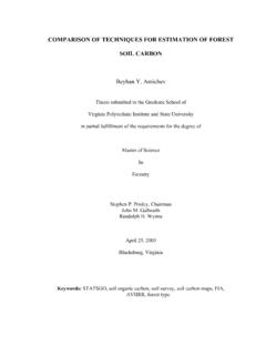
1 Fu-hua Huang Chapter 2. Convolutional Codes4 Chapter 2. Convolutional CodesThis Chapter describes the Encoder and decoder structures for Convolutional Encoder will be represented in many different but equivalent ways. Also, the maindecoding strategy for Convolutional Codes , based on the Viterbi Algorithm, will bedescribed. A firm understanding of Convolutional Codes is an important prerequisite tothe understanding of turbo Encoder StructureA Convolutional code introduces redundant bits into the data stream through theuse of linear shift registers as shown in Figure ++DD+DDDx(1)x(2)c(1)c(2)c(3)Figure : Example Convolutional Encoder where x(i) is an input information bit stream and c(i) is an output encoded bit stream [Wic95].The information bits are input into shift registers and the output encoded bits are obtainedby modulo-2 addition of the input information bits and the contents of the shift connections to the modulo-2 adders were developed heuristically with no algebraic orcombinatorial code rate r for a Convolutional code is defined asrkn=( ) Fu-hua Huang Chapter 2.
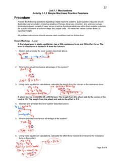
2 Convolutional Codes5where k is the number of parallel input information bits and n is the number of paralleloutput encoded bits at one time interval. The constraint length K for a Convolutional codeis defined asKm=+1( )where m is the maximum number of stages (memory size) in any shift register. The shiftregisters store the state information of the Convolutional Encoder and the constraint lengthrelates the number of bits upon which the output depends. For the Convolutional encodershown in Figure , the code rate r=2/3, the maximum memory size m=3, and theconstraint length K= Convolutional code can become very complicated with various code rates andconstraint lengths. As a result, a simple Convolutional code will be used to describe thecode properties as shown in Figure ++c(2)c(1)x(1)Figure : Convolutional Encoder with k=1, n=2, r=1/2, m=2, and K= Encoder RepresentationsThe Encoder can be represented in several different but equivalent ways.
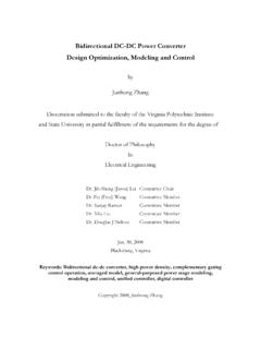
3 They are1. Generator Representation2. Tree Diagram Representation3. State Diagram Representation4. Trellis Diagram RepresentationFu-hua Huang Chapter 2. Convolutional Generator RepresentationGenerator representation shows the hardware connection of the shift register tapsto the modulo-2 adders. A generator vector represents the position of the taps for anoutput. A 1 represents a connection and a 0 represents no connection. For example,the two generator vectors for the Encoder in Figure are g1 = [111] and g2 = [101]where the subscripts 1 and 2 denote the corresponding output Tree Diagram RepresentationThe tree diagram representation shows all possible information and encodedsequences for the Convolutional Encoder . Figure shows the tree diagram for theencoder in Figure for four input bit 01 10 00 00 01 11 11 11 01 01 00 10 10 11 10 00 11 00 01 11 00 11 10 00 11 01 00 10 01 1t= 0t= 1t= 2t= 3t= 4 Figure : Tree diagram representation of the Encoder in Figure for four input bit the tree diagram, a solid line represents input information bit 0 and a dashed linerepresents input information bit 1.
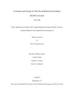
4 The corresponding output encoded bits are shown onthe branches of the tree. An input information sequence defines a specific path throughthe tree diagram from left to right. For example, the input information sequenceFu-hua Huang Chapter 2. Convolutional Codes7x={1011} produces the output encoded sequence c={11, 10, 00, 01}. Each inputinformation bit corresponds to branching either upward (for input information bit 0) ordownward (for input information bit 1) at a tree State Diagram RepresentationThe state diagram shows the state information of a Convolutional Encoder . Thestate information of a Convolutional Encoder is stored in the shift registers. Figure the state diagram of the Encoder in Figure 00 10 01 10/001/110/101/011/100/011/000/11 Figure : State diagram representation of the Encoder in Figure the state diagram, the state information of the Encoder is shown in the circles.
5 Eachnew input information bit causes a transition from one state to another. The pathinformation between the states, denoted as x/c, represents input information bit x andoutput encoded bits c. It is customary to begin Convolutional encoding from the all zerostate. For example, the input information sequence x={1011} (begin from the all zerostate) leads to the state transition sequence s={10, 01, 10, 11} and produces the outputencoded sequence c={11, 10, 00, 01}. Figure shows the path taken through the statediagram for the given Huang Chapter 2. Convolutional Codes81 00 10 01 10/001/110/101/011/100/011/000/11 Figure : The state transitions (path) for input information sequence {1011}. Trellis Diagram RepresentationThe trellis diagram is basically a redrawing of the state diagram.
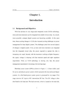
6 It shows allpossible state transitions at each time step. Frequently, a legend accompanies the trellisdiagram to show the state transitions and the corresponding input and output bit mappings(x/c). This compact representation is very helpful for decoding Convolutional Codes asdiscussed later. Figure shows the trellis diagram for the Encoder in Figure Huang Chapter 2. Convolutional Codes9 States0 00 11 01 1 Time01234 TRELLIS DIAGRAMS tates0 00 11 01 1 Timeii+10/001/110/111/000/101/010/011/10 LEGENDS tates0 00 11 01 1 Figure : Trellis diagram representation of the Encoder in Figure for four input bit shows the trellis path for the state transitions in Figure 00 11 01 1 Time01234 TRELLIS DIAGRAM1/110/101/001/01 Figure : Trellis path for the state transitions in Figure Huang Chapter 2.
7 Convolutional Catastrophic Convolutional CodeCatastrophic Convolutional code causes a large number of bit errors when only asmall number of channel bit errors is received. This type of code needs to be avoided andcan be identified by the state diagram. A state diagram having a loop in which a nonzeroinformation sequence corresponds to an all-zero output sequence identifies a catastrophicconvolutional code. Figure shows two examples of such : Examples of catastrophic Convolutional Hard-Decision and Soft-Decision DecodingHard-decision and soft-decision decoding refer to the type of quantization used onthe received bits. Hard-decision decoding uses 1-bit quantization on the received channelvalues. Soft-decision decoding uses multi-bit quantization on the received channelvalues. For the ideal soft-decision decoding (infinite-bit quantization), the receivedchannel values are directly used in the channel decoder.
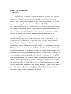
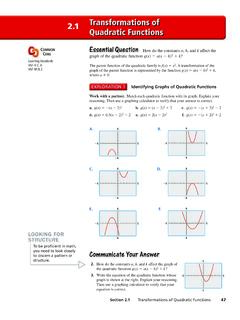
8 Figure shows hard- and soft-decision Huang Chapter 2. Convolutional Codes11 ConvolutionalEncoderBPSKM odulatorc=0 -> send -1c=1 -> send +1 ChannelBPSKD emodulatorConvolutionalDecoderHard-Decis ionrin<=0 -> rout=0rin>0 -> rout=1 NoisexcySoft-Decisionrr=routrinFigure : Hard- and Soft-decision decoding [Woe94]. Hard-Decision Viterbi AlgorithmFor a Convolutional code, the input sequence x is convoluted to the encodedsequence c. Sequence c is transmitted across a noisy channel and the received sequence ris obtained. The Viterbi algorithm computes a maximum likelihood (ML) estimate on theestimated code sequence y from the received sequence r such that it maximizes theprobability p(r|y) that sequence r is received conditioned on the estimated code sequencey. Sequence y must be one of the allowable code sequences and cannot be any arbitrarysequence.
9 Figure shows the described system : Convolutional code system. For a rate r Convolutional code, the Encoder inputs k bits in parallel and outputs nbits in parallel at each time step. The input sequence is denoted asx=(x0(1), x0(2), .., x0(k), x1(1), .., x1(k), xL+m-1(1), .., xL+m-1(k))( )and the coded sequence is denoted asc=(c0(1), c0(2), .., c0(n), c1(1), .., c1(n), cL+m-1(1), .., cL+m-1(n)) ( )where L denotes the length of input information sequence and m denotes the maximumlength of the shift registers. Additional m zero bits are required at the tail of theFu-hua Huang Chapter 2. Convolutional Codes12information sequence to take the Convolutional Encoder back to the all-zero state. It isrequired that the Encoder start and end at the all-zero state.
10 The subscript denotes thetime index while the superscript denotes the bit within a particular input k-bit or output n-bit block. The received and estimated sequences r and y can be described similarly asr=( r0(1), r0(2), .., r0(n), r1(1), .., r1(n), rL+m-1(1), .., rL+m-1(n))( )andy=(y0(1), y0(2), .., y0(n), y1(1), .., y1(n), yL+m-1(1), .., yL+m-1(n)).( )For ML decoding, the Viterbi algorithm selects y to maximize p(r|y). Thechannel is assumed to be memoryless, and thus the noise process affecting a received bitis independent from the noise process affecting all of the other received bits [Wic95].From probability theory, the probability of joint, independent events is equivalent to theproduct of the probabilities of the individual events. Thus,ppryprypryiii iininiLm(| )[ ( | ) ( |)( |)]() ()() ()() ()ry==+ 112 201 [Wic95]( ) = ==+ pr yijijjniLm(| )()()101 [Wic95]( )This equation is called the likelihood function of y given that r is received [Vit71].