Transcription of Chapter 2 Design for Shear - Faculty of Engineering
1 Chapter 2 Design for Shear By Richard W. Furlong Introduction Shear is the term assigned to forces that act perpendicular to the longitudinal axis of structural elements. Shear forces on beams are largest at the supports, and the Shear force at any distance x from a support decreases by the amount of load between the support and the distance x. Under uniform loading, the slope of the Shear diagram equals the magnitude of the unit uniform load. Shear forces exist only with bending forces. Concrete beams are expected to crack in flexure, with such cracks forming perpendicular to longitudinal tension reinforcement, , perpendicular also to a free edge.
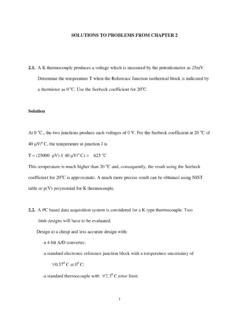
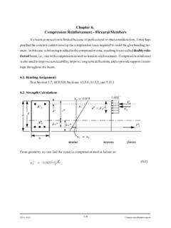
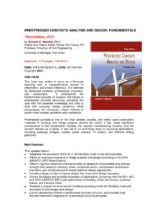
2 Principal tension stresses change direction from horizontal at the longitudinal reinforcement to 45o at the neutral axis and vertical at the location of maximum compression stress. Consequently, cracks in concrete tend to point toward the region of maximum compression stress as indicated by the cracks shown in Fig. Axial compression force plus bending makes the area of compressed concrete larger than without axial force. ACI 318-05 permits the evaluation of Shear capacity for most beams to be taken as the combination of strength from concrete without Shear reinforcement Vc plus the strength Vs provided by Shear reinforcement. Shear strength of a slab that resists flexural forces in two orthogonal directions around a column (flat plates, footings and pile caps), is evaluated as the Shear strength of a prism located at a distance of half the slab depth d from the faces of the column.
3 Neutral axisNeutral axis Span region Support region Fig. Reinforced concrete beam in bending Shear strength of beams Equation (11-3) of ACI 318-05, Section permits the Shear strength Vc of a beam without Shear reinforcement to be taken as the product of an index limit stress of 2 fc times a nominal area bwd. With fc expressed in lb/in2 units and beam dimensions in inches, nominal Shear strength Vc = 2 fc bwd in units of lb. Shear reinforcement is not required for slabs, which can be considered as very wide beams. If the width of a beam is more than twice the thickness h of the beam, ACI 318-05, Section (c) exempts such beams from the requirement of Shear reinforcement as long as the Shear capacity of the concrete is greater than the required Shear force.
4 A more complex method for determining Vc is given in ACI 318-05, Section The method is demonstrated in Shear EXAMPLE 2. A special type of ribbed floor slab known as a joist system can be constructed without any Shear reinforcement in the joist ribs. Joist system relative dimensions, slab thickness, rib width and spacing between ribs are specified in ACI 318-05, Section A diagonal crack that might result in Shear failure, as suggested in , can form no closer to the face of the support than the distance d from the face of the support. Consequently, Section of ACI 318-05 permits the maximum required value of Shear Vu to be determined at a distance d from the face of such a support when the support provides compression resistance at the face of the beam opposite the loading face.
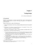
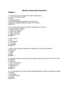
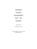
5 If loads had been suspended from the bottom of the beam, or if the support were no deeper than the beam itself, maximum required Shear must be taken as the Shear at the face of the support. The most common form of Shear reinforcement is composed of a set of bars bent into U-shaped stirrups as indicated by the vertical bars in Fig. The stirrups act as tension hangers with concrete performing as compression struts. Shear Reinforcement for Beams45oShear cracks are pinnedVcdtogether by s s sVs= Avfyd/sStandard U-stirrup Av= 2 Abarhas 2 legs. Fig. Shear reinforcement Each vertical leg of a stirrup has a tension capacity equal to its yield strength, and the most common stirrup has 2 vertical legs.
6 The Shear capacity of vertical stirrups is the tension strength of one stirrup times the number of stirrups that interrupt potential cracks on a 45-degree angle from the tension steel. Thus, Vs = Avfyd/s. A U-stirrup has an area Av = 2(area of one stirrup leg). Shear capacity at any location along a beam Vn = Vc plus Vs. d Designing stirrup reinforcement for beams Shear reinforcement Av must provide the strength required in addition to the strength of concrete Vc. Thus, the required amount of Av = (Vn Vc)/(fytd/s). The strength reduction factor for Shear is Vn must be greater than Vu. When the quantities Av, fy and d are known, stirrup spacing s can be computed as s = ( Avfytd) / (Vu - Vc) ( ) ACI 318, Section requires the placement of Shear reinforcement in all beams for which the required strength is more than half the value of Vc.
7 The full development of a critical Shear crack between stirrups is prevented by ACI 318-05, Section , which sets the maximum spacing of stirrups at d/2 when Vu < 6 Vc, but maximum spacing is d/4 when Vu > 6 Vc. Concrete cannot act effectively as compression struts if the required amount of Vs exceeds 8Vc = 8bwd fc regardless of Shear reinforcement. Thus, a beam section must be made larger if Vn > 10bwd fc . A graph given in Design aid Shear 1 displays limits of nominal Shear stress values of Vn/(bwd) for concrete strength fc from 3000 psi to 10,000 psi. The graph is not intended for precise evaluation of member capacity, as precise strength values are given in other Design aids.
8 Rather, the graphs clearly show stress ranges for which Design requirements change. No Shear reinforcement (stirrups) are required if Vn/(bwd) is less than fc . The capacity Vc of concrete in sections reinforced for Shear is fc . The strength of stirrups can be added to the concrete strength Vc to determine the total strength of a section. Required stirrups must be spaced no more than d/2 apart where Vn/(bwd) < fc . Where Vn/(bwd) > fc , maximum stirrup spacing becomes d/4. The compressive strut capacity of concrete is reached if Vn/(bwd) = fc . Additional stirrups cannot increase section Shear strength, as the concrete strength is considered exhausted when Vn/(bwd) > 10 fc.
9 Design aid Shear 2 consists of 3 tables that may be used to determine Shear capacity for rectangular sections of width b or bw from 10 in to 32 in and thickness h from 10 in to 48 in. It is assumed that depth d is inches less than thickness for h < 30 in, but that larger longitudinal bars would make d h 3 in for deeper beams. Table 2a gives values Kfc = (fc /4000) to be used as modifiers of Kvc when members are made with concrete strength different from fc = 4000 psi. In conjunction with required stirrups, the nominal Shear strength of concrete Vc = KfcKvc. Table 2b contains values Kvs for determining nominal stirrup capacity Vs = Kvs(Av/s).
10 Table 2c gives values Kvc in kips. Kvc is the Shear strength of concrete when required stirrups areused in members made with fc = 4000 psi concrete. The nominal strength of a rectangular section is the sum of concrete strength Vc and reinforcement strength Vs to give Vn = KfcKvc + Kvs(Av/s). Shear 3 is a Design aid for use if Grade 60 stirrups larger than #5 are to be used, and sections must be deep enough for tension strength bar development of larger stirrups or closed ties. Required thickness of section values are tabulated for concrete strengths from 3000 psi to 10,000 psi and for #6, #7 and #8 stirrups. It should be noted that ACI 318 05, Section limits the yield strength of reinforcing bar stirrups to no more than 60,000 psi.