Transcription of D. Chapter 3. Compression - University of Memphis
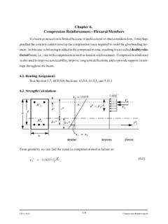
1 37 3. Chapter 3. AXIALLY LOADED MEMBERS Reading Assignment: Section and Sections and of text.. Most axially loaded structural members carry some moment in addition to axial load - for this discussion, restrict consideration to axial load only. Reinforcement of Compression Members Plain concrete columns prohibited: possibility of bending is always present: ACI : As/Ag ACI : where As = Area of longitudinal reinforcement; Ag = Total area of column cross section; Possible column configuration a. Tied - Deformed bars or wires placed normal to column axis CIVL 4135 Chapter 3. AXIALLY LOADED MEMBERS 38 CIVL 4135 Chapter 3. AXIALLY LOADED MEMBERS 39 Spacing of Ties to Prevent Longitudinal Bar Buckling A. Tied column may fail prior to steel yield if shell spalls and longitudinal bars buckle; B.
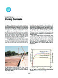
2 Insure that bar buckling load is greater than yield load. ( cr > fy) Assume that bar buckling load is greater than yield load - Assume a pin-pin bar between ties: 22crEIPL = ( ) The moment of inertia of a circular bar is: 464DI = ( ) and for cr = Pcr/A = Pcr/( D2/4) 2216( / )crELD = ( ) Example: For fy = 40 ksi = cr 2224016( / )16( / )crEELDLD = = ( ) Solving for critical buckling condition L = 21 D So, to prevent buckling, space ties more closely than this. ACI Code requires (ACI, Sect ) that spacing not to be greater than 16 D (D = Diameter of longitudinal bar); 48 tie bar diameter; Least member dimension. Other Code requirements are given in ACI Sections CIVL 4135 Chapter 3. AXIALLY LOADED MEMBERS 40 b. Spiral: Circular arrangement of longitudinal bars confined by a continuous wire which spirals around the bars for the entire length of the member; c.
3 Composite and combination: Structural steel member encased in concrete or steel pipe filled with concrete ACI : at least 4 bars in tied columns at least 6 bars in spiral columns at least 3 bars in triangular ties Tied or spiral columns are used in order: to prevent buckling of longitudinal bars to prevent movement of longitudinal bars during construction. Bundles of steel bars are sometimes used to prevent congestion. It is shown that they act as a unit with area as the same as all of the bundle bars. In buildings columns generally have proportions with the ratio of length to cross section width (L/h) in the range from about 8 to 12. (use of high strength, more slender column becoming more popular.) Design Assumptions: A. Strain compatibility between steel and concrete (to prefect bonding; no slip; mechanical interlocking).
4 Longitudinal Rodsand spiral hoopingCIVL 4135 Chapter 3. AXIALLY LOADED MEMBERS 41 B. Axially loaded Uniform strain over cross section; Axial load plus vary linearly; Moment Strains vary linearly. a. Concrete tensile strength usually zero. b. The internal forces must be in equilibrium with applied external loads. c. Plane cross section remains plane after application of loading. d. Theory is based on real strain-stress relationships. Elastic behavior of column Example (See ACI section ) 1. Up to 12ccff concrete stress-strain approximately linear. This is known as the working or service load range: 2. For strain equality in this range: csscssccscffEorffEEE ===== ( ) letting fs = n fc Note: n is generally rounded to the nearest whole no. CIVL 4135 Chapter 3.
5 AXIALLY LOADED MEMBERS 42 Adopting the following notation: Ag = gross section area, (in2) As = area of steel (in2) Ac = net concrete area = Ag - As P = Axial force on column Then P = Acfc + Asfs = Acfc + nfcAs = fc(Ac + nAs) Transformed area The three bars along each of the two faces are thought of as being removed and replaced, at the same distance from the axis of the section, with added areas of fictitious concrete of total amount of nAs. Alternatively, as shown in figure c, we can think of the area of the steel bars as replaced with concrete in which case one has to add to the gross concrete area Ag so obtained only (n -1)As in order to obtain the same total transformed area. So, knowing Ac = Ag - As P = fc(Ag + (n-1)As) CIVL 4135 Chapter 3. AXIALLY LOADED MEMBERS 43 Example 1 Given: 4 # 8 bars Assume: cf = 4000 psi fy = 40 ksi area of steel = 4(area of # 8 bars) 4( ) = (see ACI 318 - bar dimension table, or page iii of class notes) AsAg = = (ACI 318 Sect.)
6 < < ) What axial load will cause concrete to be at its maximum working stress? Solution: []40002000257,000 4000 3,600,00029,000,000()29,000, 83,600,000( ( 1) ) 2000 144 (8 1)( ) 332,000332csscccssccgsfpsiEffnfEEpsiEpsialwaysEThereforenEPf AnAlbskipsboth steel and concrete beha======= === =+ = ==ve elastically ( ) CIVL 4135 Chapter 3. AXIALLY LOADED MEMBERS 44 Example 2 For the previous example find the axial load P which produces c = s = CIVL 4135 Chapter 3. AXIALLY LOADED MEMBERS 45 Nominal axial load of column Pn ; (Pu = Pn) - Greatest calculated load A. Should occur when concrete stress peaks, steel reaches yield - assume this condition. B. Concrete stress will not be cf : cf based on test of standard cylinder; ends confined.; cf depends on the rate of loading; Strength of actual column varies over length - water migrates to top, causing top to be slightly weaker.
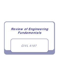
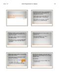
7 Use fc = cf at nominal load condition then PN = Acfc + Asfs = Ac( ) + Asfy for column of previous example: PN = (144 - )( )(4000) + (40,000) = 605 kips CIVL 4135 Chapter 3. AXIALLY LOADED MEMBERS 46 Example 3 Consider a rectangular column subjected to axial Compression . The material stress-strain relationships have been idealized as shown below. 1. Determine the stress in the concrete and stress in the steel if the applied load is equal to 3100 kips. 2. Determine the stress in the concrete and stress in the steel if the applied load is equal to 4050 kips. See the solution on the next page. CIVL 4135 Chapter 3. AXIALLY LOADED MEMBERS 47 CIVL 4135 Chapter 3. AXIALLY LOADED MEMBERS 48 Behavior of Spirally Reinforced Columns Confinement A. ACI spiral reinforcement ratio based on tests by Richart, Brandtzeg and Brown - 1928; (Univ.)
8 Of Illinois experimental bulletin no. 185). Using 6 x 12 cylinders, they related lateral confining pressure to axial capacity; CIVL 4135 Chapter 3. AXIALLY LOADED MEMBERS 49 where f*c =Compressive strength of spirally confined core concrete cf = compressive strength of concrete if unconfined 2f = lateral confinement stress in core concrete produced by spiral CIVL 4135 Chapter 3. AXIALLY LOADED MEMBERS 50 Spiral ColumnCIVL 4135 Chapter 3. AXIALLY LOADED MEMBERS 51 CIVL 4135 Chapter 3. AXIALLY LOADED MEMBERS 52 CIVL 4135 Chapter 3. AXIALLY LOADED MEMBERS 53 B. What sort of lateral confinement can a given spiral provide? Consider a length of a spiral-wrapped circular section: for a length S : volume of spiral = Asp D (approximately) volume of concrete = ( D2/4)S Let s = volume of spiralvolume of concrete = 4 AspDS Calculate equivalent confinement: f 2DS = 2 Aspfys or f 2 = ( s fys)/2 from previous research: ** =+=+ =+ ACI objective is to insure that PB > PN.
9 Therefore, make sure spiral increases capacity of core enough to make up for loss of shell. Before shell spalls: PN = Asfy + c(Ag - As) After shell spalls: PB = Asfy + (Acore - As)( c + 2 sfys) sAspDCIVL 4135 Chapter 3. AXIALLY LOADED MEMBERS 54 Set PB = PN, calculate like terms, expand: ( )( )2sycgcssycorecsysscssysAffAfAAfAffAfAf + =++ Ignore the last term - very small then () (2)cgcorecoresysfAAAf = ( ) solve for spiral reinforcement ratio we have: () (2)cgcorescoreysfAAAf = ( ) or = ( ) conservatively, change to to get Eq. 10-6 of ACI: (.106)gcsyscoreAfACI EqfA = ( ) which says that the ratio of spiral reinforcement shall not be less than the value given by the equation above; where fy is the specified yield strength of spiral reinforcement but not more than 60,000 psi.
10 Maximum Loads for Spiral Column Prior to spalling of shell: same as tied column () ANsycgsPPAffAA ==+ ( ) after spalling of shell: () ( 2)BsycorescsysPAfAAff =+ + ( ) or CIVL 4135 Chapter 3. AXIALLY LOADED MEMBERS 55 ()() (2)BsycoresccoressysPAfAAfAAf =+ + ( ) The underlined term is the added capacity of the core resulting from the presence of the spiral. where will s be critical? High strength concrete (shell carries large loads); Small columns or square columns; Columns with large cover. Example - Ultimate Strength of Spiral Column Choose a column with areas equivalent to those of previous example (page ) Ag = 144 in2 f c = 4000 psi Acore = ( ( )2/4) = in2 fy = 40 ksi As = in2 s = in fys = 50 ksi Use (3/8) diameter spiral: Asp = AsAg = = s = 4 AspDS = 4 = Check spiral ratio against ACI requirements (4) = = = ( ) Since > , the column satisfies the minimum spiral reinforcement requirements.