Transcription of CHAPTER 3 Heat Exchanger Design - ChE 192
1 CHAPTER 3 heat Exchanger Design This CHAPTER will provide the framework on how to Design a Double Pipe and Shell and Tube type heat Exchanger . Detailed theoretical discussion on the principles of heat transfer was consciously left to readers to read standard textbook in heat transfer. A brief review of every topic that would be needed in the understanding of heat Exchanger Design has been provided to assure continuity and comprehension. A double-pipe heat Exchanger is consists of two concentric pipes with one fluid flowing through the inner pipe while the other fluid flowing through the annular space .While a shell-and-tube heat Exchanger consists of tube bundles enclosed in a cylindrical shell with one fluid flowing through the tubes and the other fluid flowing outside of the tube bundles enclosed in the shell.
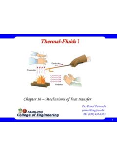
2 The three fundamental mode of heat transfer are (1) conduction, (2) convection and (3) radiation. Conduction occurs when the transfer of heat is through molecular action. There is a need of physical contact but without significant displacement or movement of molecules. It could take place within a solid or non-moving fluid medium. On the other hand, convection requires the movement or mixing of fluids. It takes place between a solid surface and a contacting moving fluid that are at different temperatures. Radiation is the transfer of heat in the form of electromagnetic waves. This mode of transfer does not require the presence of an intervening material or physical contact . heat Exchanger Design EQUATIONS Rate of heat Transfer Similar to other transport phenomena, the rate of heat transfer is also expressed in terms of driving force and resistance.
3 The general rate expression for heat transfer is conveniently expressed in terms of overall heat -transfer coefficient, U, which is defined in an analogous manner to Newton s law for convective heat transfer. For Double Pipe heat Exchanger , the rate of heat transfer may be computed using Equation 3-1. lnTUAq eq 3-1 However, to correct mixed flow in a shell and tube type of heat exchangers, a geometric correction factor, Y, has to be added to account for the flow deviation from double Pipe heat exchangers. Thus, lnTUAYq eq 3-2 where: A = total heat -transfer area in the heat Exchanger 21,TT = temperature difference between hot and cold streams at heat Exchanger terminals lnT = logarithmic mean temperature difference (LMTD) heat Exchanger Design 2 )/ln(1212lnTTTTT eq 3-3 Y is correlated to two dimensionless temperature ratios namely the heat capacity Z, and the effectiveness of the heat Exchanger X.
4 Values of the geometric correction factor for different number of tube to shell passes may be derived from Figure 3-1 and 3-2. 1B1A1B2BB2B2A1 ATTTTXand1 TTTTZ eq 3-4 Figure 3-1. Correction factor for mixed-flow Type heat Exchangers one shell pass; two or more tube passes. Adapted from ASME as cited by Foust, 1980. Rearranging equation---- and expressing in terms of resistance, lnTUAYRTq eq 3-5 heat Exchanger Design 3 Thus UAR1 eq 3-6 The Overall heat transfer coefficient maybe based on the inside, Ui or based on the outside, Uo . The choice of overall heat transfer coefficient would depend on which of the resistances would be controlling or bigger.
5 While overall heat transfer coefficient is directly proportional to convective heat transfer coefficient, convective resistance is inversely proportional to the convective heat transfer coefficient. Thus, the lower the convective heat transfer coefficient the more controlling its resistance. If ho <<< hi, then Ro >>> Ri thus lnTYAUqoo eq 3-7 Figure 3-2. Two Shell passes; four tube passes. Adapted from ASME as cited by Foust, 1980. heat Exchanger Design 4 On the other hand, if hi <<< ho Then Ri >>> Ro Thus lnTAUqii eq 3-8 In a steady-state transfer of heat from a hot fluid stream outside the tube to a cold fluid stream inside the tube, the following steps are involved: convection from the hot fluid outside the tube to a tube wall surface, conduction through the tube wall, and convection from the surface to the cold fluid flowing inside the tube.
6 Thus, a 3- resistance overall heat transfer coefficient is, oowwiiiiooAhmAkxAhAUAUR1111 eq 3-9 If outside film resistance is controlling, Equation 3-9 is reduced to, owwiohDmkDoxDihDoU11 eq 3-10 Whereas if the inside film resistance is controlling , the working equation would be: DohDiDmkDoxhUiowwi11 eq 3-11 However if fouling exits in both sides of the wall, additional scale resistances will be incorporated, AohRandAihRofofifif,,,,11 eq 3-12 where hf,i and hf,o are the fouling coefficients of the inside and outside surfaces of the tube, respectively. Thus , the overall resistance , U , is: oofoowwiifiiiiooAhAhmAkxAhAhAUAUR,,11111 1 eq 3-13 A similar simplified equation may be derived for known controlling film resistance. heat Exchanger Design 5 Table 3-1 shows typical fouling factor for different liquids at different fluid velocity.
7 Table 3-1. Typical Fouling factor (Foust, 1980). Fouling Factor, Rd = 1/hd hr F ft2/Btu Water Velocity 3 ft/s or less 3 ft/s or more Seawater (up to 125 F) Well water Delaware and Lehigh river waters Brine Fuel oil Conductive heat Transfer Fourier s Law of heat Conduction states that the heat flux , q/A, (the rate of heat transfer per unit time per unit area) is proportional to the temperature gradient (-)dT and inversely wall thickness: dxdTkAq eq 3-14 )()(1212xxTTk eq 3-15 where: )(12xxx, thickness of the wall )(21 TTT, temperature drop across wall )(kAxR, conductive thermal resistance of wall Where the proportionality constant k is the thermal conductivity that indicates how good the material conducts thermal energy.
8 In most engineering applications k may be considered constant except in high temperature drops. In cases where k varies with temperature a linear relationship such as in Equation 3-16 may be used (McCabe, 2001): bTak eq 3-16 Where a and b are empirical constants and T is the temperature of the medium. In case of radial conduction of heat in a hollow cylindrical vessels or pipes, the area perpendicular to the direction of heat flow is not constant but is proportional to the radius (rLA2). Thus, for hollow cylindrical configurations with outside radius ro to inside radius ri, ratio is greater than (Mc Cabe): RTrrTTAkrrTTLkqiooiLiooi)()()/ln())(2( eq 3-17 heat Exchanger Design 6 where: LioAkrrR)( eq 3-18 LrALL)2( (Logarithmic mean surface area) eq 3-19 )r/rln()rr(rioioL (Logarithmic mean radius) eq 3-20 In cases where the outside to inside radius ratio is less , logarithmic mean radius will just be equal to average radius.
9 Series of Resistances At steady-state, the rate of heat transfer through a wall consisting of a series of layers of different conducting media A, B, C .. that are in excellent thermal contact will be equal to the rate of heat transfer in each layer, CBAqqqq eq 3-21 The total temperature drop across the multilayer wall is equal to the sum of the temperature drops across each layer, CBATTTT eq 3-22 Whereas the total resistance of the multilayer wall is equal to the sum of the individual resistances, CBARRRRqT/ eq 3-23 Where resistance for each layer is: )(AkxqTRAAAAA eq 3-24 )(AkxqTRBBBBB eq 3-25 )(AkxqTRCCCCC eq 3-26 heat Exchanger Design 7 Convective heat Transfer Newton s Law for Convective heat Transfer states that the convective heat flux is proportional to the difference between the surface temperature, Tw, and the temperature of the fluid Tf along the heat flow path: )TT(hAqfw eq 3-27 R = hA1 eq 3-28 Where.
10 R = Convective resistance h = Convective heat transfer coefficient (local film coefficient) A = heat transfer area in-contact with the fluid Several empirical equations were derived to estimate convective heat transfer applicable coefficient for different types of heat exchangers that operates as heaters, condensers, reboiler and evaporators. heat Transfer without Phase Change This section covers the estimation of convective heat transfer coefficient of fluids involve in heating and cooling in Double Pipe and Shell and tube type of heat Exchangers. Double Pipe heat Exchanger The Sieder-Tate equation is applicable in the estimation of the convective heat transfer coefficient of fluids flowing inside the tube of a double pipe heat Exchanger .