Transcription of Chapter 5 Compact Heat Exchangers (Part III)
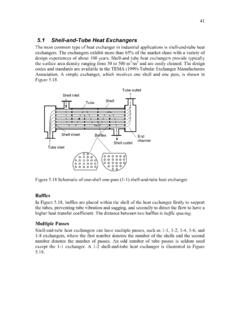
1 109 Chapter 5 Compact heat Exchangers ( part III) Plate-Fin heat Exchangers Plate fin Exchangers have various geometries of fins to compensate the high thermal resistance by increasing the heat transfer area particularly if one of fluids is air or gas. This type of exchanger has corrugated fins sandwiched between parallel plates or formed tubes. The plate fins are categorized as triangular fin, rectangular fin, wavy fin, offset strip fin (OSF), louvered fin, and perforated fin. One of the most widely used enhanced fin geometries is the offset strip fin type, which is shown in Figure Plate$fin heat Exchangers have been introduced since the 1910s in the auto industry, since the 1940s in the aerospace industry.
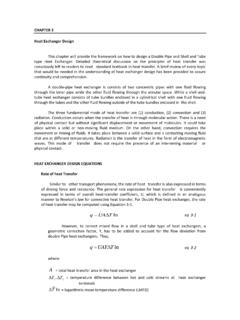
2 They are now used widely in many industries for aircraft, cryogenics, gas turbine, nuclear, and fuel cell. Plate$fin heat Exchangers are generally designed for moderate operating pressures less than 700 kPa (gauge pressure) and have been built with a surface area density of up to 5900 m2/m3. Common fin thickness ranges between and mm. Fin heights may range from 2 to 25 mm. Although typical fin densities are 120 to 700 fins/m, applications exist for as many as 2100 fins/m [17]. L3L1L2 Air (fluid 2)Gas (fluid 1)AirGas b2b1 Figure Plate$fin heat exchanger , employing offset strip fin. 110 abcdefghijklb1(b2 for fluid 2) w wpf PlatePlate (pf - )(b1 - ) Figure Schematic of offset strip fin (OSF) geometry Geometric Characteristics A schematic of a single$pass crossflow plate$fin heat exchanger , employing offset strip fins, is shown in Figure The idealized fin geometry is shown in Figure Defining the total heat transfer area for each fluid is important in the analysis.
3 The total area consists of the primary area and the fin area. The primary area consists of the plate area except the fin base area, multi$passage side walls, and multi$passage front and back walls. It is practical to assume that the numbers of passages for the hot fluid side and the cold fluid side are Np and Np +1 to minimize the heat loss to the ambient. The top and bottom passages in Figure are designated to be cold fluid. The number of passages (don t confuse with the number of passes) can be obtained from an expression for L3 as {()()4342143421plates totalof thickness2 fluid oflength 21 fluid oflength 13121wpppNbNbNL ++++= ( ) Solving for Np gives the number of passages for hot fluid wwpbbbLN 222123++ = ( ) By definition, the number of passages counts the number based on one flow passage between two plates, not all the individual channels between the plates.}
4 The total number of fins for fluid 1 (hot) is calculated by pffNpLn111= ( ) For fluid 2 (cold), ()1222+=pffNpLn ( ) 111 where pf1 is the fin pitch that is usually obtained by making inverse of the fin density. The total number of fins nf1 is based on the shaded area (a$c$d$e$f$g$h$j$a) in Figure counting as the unit fin. Since total primary area = total plate areas fin base areas + passage side wall areas + passage front and back wall areas, the primary area for fluid 1 is expressed by ()()444 3444 21434214342143421area back wall andfront passage12area wallside passage21area basefin 12area plate total211122222++++ =pwpfppNLbNLbnLNLLA ( ) The number of offset strip fins noff1 per the number of fins is obtained by 212 Lnoff= ( ) 121 Lnoff= ( ) where 1,2 is the offset strip fin length for fluid 1 and 2.
5 The total fin area Af1 consists of the fin area and offset$strip edge areas. ()()()()43421444 3444 2144 344 2144 344 21a)$j$i$b$2(a ,area edge strip$offsetlast &1st 11i)$l$k$j$2(iarea edge strip$offset internal111e)$d$c$2(bareas edge strip$offset111f)$g and e$(dareas surfacefin 12112122fffoffffoffffnpnnpnnbnLbA + + + = ( ) Note that the cross$shaded area (a$b$l$k$a) was not included in the offset$strip edge area because the area is closely blocked by the next strip fin as shown in Figure so that no heat transfer at the area is expected. The total heat transfer area At1 is the sum of the primary area and the fin area as 111fptAAA+= ( ) The free$flow (cross sectional) area Ac1 is obtained by ()()1111ffcnpbA = ( ) It is assumed in Equation ( ) that there exists a small gap between the offset strip fins, whereby the next strip fin shown in the unit fin in Figure is not considered as an obstructing structure to the free flow.
6 The frontal area Afr1 for fluid 1 where fluid 1 is entering is defined by 311 LLAfr= ( ) 112 The hydraulic diameter for fluid 1 is generally defined by 12114tchALAD= ( ) For the fin efficiency f of the offset strip fin, it is assumed that the heat flow from both plates is uniform and the adiabatic plane occurs at the middle of the plate spacing b1. Hence, the fin profile length Lf1 is defined by =211bLf ( ) The m value is obtained using Equation ( ) as +=1112 fkhm ( ) The single fin efficiency f is obtained using Equation ( ) by ()1111tanhfffLmLm= ( ) The overall surface (fin) efficiency o is then obtained using Equations ( ), ( ) and ( ) as ()ftfoAA =11111 ( ) Correlations for Offset Strip Fin (OSF) Geometry This geometry has one of the highest heat transfer performances relative to the friction factors.
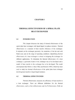
7 Extensive analytical, numerical and experimental investigations have been conducted over the last 50 years. The most comprehensive correlations for j and f factors for the laminar, transition, and turbulent regions are provided by Manglik and Bergles [27] in 1995 as follows. 113 + = ffffpbppbpj ( ) + = ffffpbppbpf ( ) where the hydraulic diameter was defined by them as ()()()( ) ( )() () + + + =fffMBhpbbpbpD24_ ( ) This is an approximation of Equation ( ). However, Equation ( ) is in excellent agreement with Equation ( ), which indicates the general definition of hydraulic diameter, Equation ( ), can be used in place of Equation ( ).
8 The correlations of Manglik and Bergles [27] were compared with the experiments (surface 1/8$ ) reported by Kays and London [8] in Figure The comparison for both j and f shows good agreement. Note that the comparison covers from laminar through turbulent regions. 1141001 103 1 104 1 103 j Figure Colburn factor j and friction factor f for offset$strip$fin (OSF) type plate$fin heat Exchangers . The correlation of Manglik and Bergles [27] were compared with the experiments (1/8$ surface) of Kays and London [8]. 115 Example Plate-Fin heat exchanger A gas$to$air single$pass crossflow heat exchanger is designed for heat recovery from the exhaust gas to preheat incoming air in a solid oxide fuel cell (SOFC) co$generation system.
9 Offset strip fins of the same geometry are employed on the gas and air sides; the geometrical properties and surface characteristics are provided in Figures and Both fins and plates (parting sheets) are made from Inconel 625 with k=18 W/mK. The anode gas flows in the heat exchanger at m3/s and 900 C. The cathode air on the other fluid side flows at m3/s and 200 C. The inlet pressure of the gas is at 160 kPa absolute whereas that of air is at 200 kPa absolute. Both the gas and air pressure drops are limited to 10 kPa. It is desirable to have an equal length for L1 and L2. Design a gas$to$air single$pass crossflow heat exchanger operating at = Determine the core dimensions of this exchanger .
10 Then, determine the heat transfer rate, outlet fluid temperatures and pressure drops on each fluid. Use the properties of air for the gas. Use alsothe following geometric information given. Description value Fin thickness mm Plate thickness w mm Fin density Nf 782 m 1 Spacing between plates b1 and b2 mm Offset strip length 1 and 2 mm L3L1L2 Air (fluid 2)Gas (fluid 1)AirGas b2b1 Figure Plate$fin heat exchanger , employing offset strip fin. 116abcdefghijklb1(b2 for fluid 2) w wpf PlatePlate (pf - )(b1 - ) Figure Schematic of offset strip fin (OSF) geometry MathCAD format solution: Design concept is to develop a MathCAD model as a function of the dimensions of the sizing and then solve the sizing with the design requirements.