Transcription of Chapter 5 Heat Exchangers - Memorial University of ...
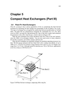
1 Chapter 5 heat IntroductionHeat Exchangers are devices used to transfer heat between two or more fluid streamsat different temperatures. heat Exchangers find widespread use in power generation,chemical processing, electronics cooling, air-conditioning, refrigeration, and automo-tive applications. In this Chapter we will examine the basic theory of heat exchangersand consider many applications. In addition, we will examine various aspects of heatexchanger design and heat exchanger ClassificationDue to the large number of heat exchanger configurations, a classification systemwas devised based upon the basic operation, construction, heat transfer, and flowarrangements.
2 The following classification as outlined by Kakac and Liu (1998) willbe discussed: Recuperators and regenerators Transfer processes: direct contact or indirect contact Geometry of construction: tubes, plates, and extended surfaces heat transfer mechanisms: single phase or two phase flow Flow Arrangement: parallel flow, counter flow, or cross flowFigure 1 shows a more comprehensive classification using these basic Equipment and heat exchanger Design MethodsThe goal of heat exchanger design is to relate the inlet and outlet temperatures,the overall heat transfer coefficient, and the geometry of the heat exchanger , to therate of heat transfer between the two fluids.
3 The two most common heat exchangerdesign problems are those ofratingandsizing. We will limit ourselves to the designof recuperators only. That is, the design of a two fluid heat exchanger used for thepurposes of recovering waste will begin first, by discussing the basic principles of heat transfer for a heatexchanger. We may write the enthalpy balance on either fluid stream to give:Qc= mc(hc2 hc1)( )andQh= mh(hh1 hh2)( )For constant specific heats with no change of phase, we may also writeQc= ( mcp)c(Tc2 Tc1)( )andQh= ( mcp)h(Th1 Th2)( )Now from energy conservation we know thatQc=Qh=Q, and that we may relatethe heat transfer rateQand the overall heat transfer coefficientU, to the some meantemperature difference Tmby means ofQ=U A Tm( )whereAis the total surface area for heat exchange thatUis based upon.
4 Later weshall show that Tm=f(Th1, Th2, Tc1, Tc2)( )It is now clear that the problem of heat exchanger design comes down to obtainingan expression for the mean temperature difference. Expressions for many flow con-figurations, parallel flow, counter flow, and cross flow, have been obtained in theheat transfer field. We will examine these basic expressions later. Two approachesto heat exchanger design that will be discussed are the LMTD method and the effec-tiveness - NTU method. Each of these methods has particular advantages dependingupon the nature of the problem Overall heat Transfer CoefficientA heat exchanger analysis always begins with the determination of the overall heattransfer coefficient.
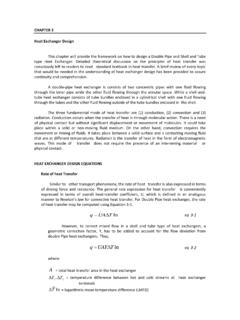
5 The overall heat transfer coefficient may be defined in terms ofHeat Exchangers107individual thermal resistances of the system. Combining each of these resistances inseries gives:1U A=1( ohA)i+1 Skw+1( ohA)o( )where 0is the surface efficiency of inner and outer surfaces,his the heat transfercoefficients for the inner and outer surfaces, andSis a shape factor for the wallseparating the two surface efficiency accounts for the effects of any extended surface which ispresent on either side of the parting wall. It is related to the fin efficiency of anextended surface in the following manner: o=(1 (1 f)AfA)( )The thermal resistances include: the inner and outer film resistances, inner andouter extended surface efficiencies, and conduction through a dividing wall whichkeeps the two fluid streams from mixing.
6 The shape factors for a number of usefulwall configurations are given below in Table 1. Additional results will be presentedfor some complex doubly connected ( ) is for clean or unfouled heat exchanger surfaces. The effects offouling on heat exchanger performance is discussed in a later section. Finally, weshould note thatU A=UoAo=UiAi( )however,Uo6=Ui( )Finally, the order of magnitude of the thermal resistances in the definition of theoverall heat transfer coefficient can have a significant influence on the calculation ofthe overall heat transfer coefficient. Depending upon the nature of the fluids, oneor more resistances may dominate making additional resistances unimportant.
7 Forexample, in Table 2 if one of the two fluids is a gas and the other a liquid, then it iseasy to see that the controlling resistance will be that of the gas, assuming that thesurface area on each side is Equipment and SystemsTable 1 - Shape FactorsGeometrySPlane WallAtCylindrical Wall2 Lln(rori)Spherical Wall4 riroro riTable 2 - Order of Magnitude ofhKakac (1991)Fluidh[W/m2K]Gases (natural convection)5-25 Gases (forced convection)10-250 Liquids (non-metal)100-10,000 Liquid Metals5000-250,000 Boiling1000-250,000 Condensation1000-25, LMTD MethodThe log mean temperature difference (LMTD) is derived in all basic heat transfertexts.
8 It may be written for a parallel flow or counterflow arrangement. The LMTDhas the form: TLMT D= T2 T1ln T2 T1( )where T1and T2represent the temperature difference at each end of the heatexchanger, whether parallel flow or counterflow. The LMTD expression assumes thatHeat Exchangers109the overall heat transfer coefficient is constant along the entire flow length of the heatexchanger. If it is not, then an incremental analysis of the heat exchanger is LMTD method is also applicable to cross flow arrangements when used with thecross flow correction factor. The heat transfer rate for a cross flow heat exchangermay be written as:Q=F U A TLMT D( )where the factorFis a correction factor, and the log mean temperature difference isbased upon the counterflow heat exchanger LMTD method assumes that both inlet and outlet temperatures are this is not the case, the solution to a heat exchanger problem becomes some-what tedious.
9 An alternate method based upon heat exchanger effectiveness is moreappropriate for this type of analysis. If T1= T2= T, then the expression forthe LMTD reduces simply to NTU MethodThe effectiveness / number of transfer units (NTU) method was developed to simplifya number of heat exchanger design problems. The heat exchanger effectiveness isdefined as the ratio of the actual heat transfer rate to the maximum possible heattransfer rate if there were infinite surface area. The heat exchanger effectivenessdepends upon whether the hot fluid or cold fluid is a minimum fluid. That is thefluid which has the smaller capacity coefficientC= mCp.
10 If the cold fluid is theminimum fluid then the effectiveness is defined as: =Cmax(TH,in TH,out)Cmin(TH,in TC,in)( )otherwise, if the hot fluid is the minimum fluid, then the effectiveness is defined as: =Cmax(TC,out TC,in)Cmin(TH,in TC,in)( )We may now define the heat transfer rate as:Q= Cmin(TH,in TC,in)( )It is now possible to develop expressions which relate the heat exchanger effective-ness to another parameter referred to as the number of transfer units (NTU). Thevalue of NTU is defined as:N T U=U ACmin( )It is now a simple matter to solve a heat exchanger problem when110 Mechanical Equipment and Systems =f(N T U, Cr)( )whereCr= expressions have been obtained which relate the heat exchanger effec-tiveness to the number of transfer units.