Transcription of Chapter 31 Alternating Current Circuits
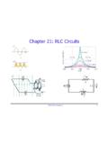
1 Chapter 31 Alternating Current CircuitsMFMcGraw-PHY 2426 Chap31-AC Circuits -Revised: 6/24/20122 Alternating Current Circuits Alternating Current - Generator Wave Nomenclature & RMS AC Circuits : Resistor; Inductor; Capacitor Transformers - not the movie LC and RLC Circuits - No generator Driven RLC Circuits - Series Impedance and Power RC and RL Circuits - Low & High Frequency RLC circuit - Solution via Complex Numbers RLC circuit - Example ResonanceMFMcGraw-PHY 2426 Chap31-AC Circuits -Revised: 6/24/20123 GeneratorsBy turning the coils in the magnetic field an emf is generated in the coils thus turning mechanical energy into Alternating (AC) 2426 Chap31-AC Circuits -Revised: 6/24/20124 GeneratorsRotating the Coil in a Magnetic Field Generates an Emf Examples: Gasoline generator Manually turning the crank Hydroelectric powerMFMcGraw-PHY 2426 Chap31-AC Circuits -Revised: 6/24/20125 Generatorsmmmpeakpeak = NBAcos = t = NBAcos td= - = NBA sin tdt=sin t.
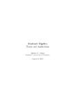
2 = NBA MFMcGraw-PHY 2426 Chap31-AC Circuits -Revised: 6/24/20126 Wave Nomenclature and RMS ValuesMFMcGraw-PHY 2426 Chap31-AC Circuits -Revised: 6/24/20127 Wave NomenclatureApeak-peak = Ap-p = 2 Apeak = 2Ap; Ap = Ap-p /2 MFMcGraw-PHY 2426 Chap31-AC Circuits -Revised: 6/24/20128 sinx = A t -cos{} sintx = A2 -cosT()() 2 22x = A sin t -x = A sin t cos - sin cos tx = A sin t (0) - (1)cos tx = -Acos tThe minus sign means that the phase is shifted to the right. A plus sign indicated the phase is shifted to the leftShifting Trig FunctionsMFMcGraw-PHY 2426 Chap31-AC Circuits -Revised: 6/24/20129 Shifting Trig Functions t -= 02 t =2 11Tt = ; =2 2 TTt ==2 2 4 sin t -= 02 Shifted T rig ( t)sin( t- )MFMcGraw-PHY 2426 Chap31-AC Circuits -Revised: 6/24/201210 Root Mean SquaredProcedure Square it (make the negative values positive) Take the average (mean) Take the square root (undo the squaring operation)The root mean squared (rms) method of averaging is used when a variable will average to zero but its effect will not average to 2426 Chap31-AC Circuits -Revised: 6/24/201211 Sine (Ra dia ns)SIN(Theta)SIN2(Theta)RMS ValueRoot Mean Squared AverageMFMcGraw-PHY 2426 Chap31-AC Circuits -Revised: 6/24/201212 Average of a Periodic Function Tavgpocos( T)T Tppavgpo0cos(0)pavg1V = V=V(t)dt.
3 V(t) = V sin tTVV1V = V sin tdt = sinxdx = - d(cosx)T T TVV= -(1 - 1) = 0 TMFMcGraw-PHY 2426 Chap31-AC Circuits -Revised: 6/24/201213 Root Mean Squared()()()() T222pavgo222 Tppp2 2avgo2p2avg2 RMSppavg1V= V=V (t)dt; V(t) = V sin tTVVVV = sin tdt = = T T2VV=21 VV=V = 2426 Chap31-AC Circuits -Revised: 6/24/201214 Root Mean Squared() 2 RMSppavg1 VV=V = RMS voltage (VRMS )is the DC voltage that has the same effect as the actual AC 2426 Chap31-AC Circuits -Revised: 6/24/201215 RMS PowerThe average AC power is the product of the DC equivalent voltage and Current .()()avgp pppRMSRMSavgRMSRMSavgRMS RMS1P= V I2 VIsince V= and I=221P=2 V2 I2P= VIMFMcGraw-PHY 2426 Chap31-AC Circuits -Revised: 6/24/201216 Resistor in an AC CircuitMFMcGraw-PHY 2426 Chap31-AC Circuits -Revised: 6/24/201217 Resistor in an AC CircuitFor the case of a resistor in an AC circuit the VR across the resistor is in phase with the Current I through the phase means that both waveforms peak at the same 2426 Chap31-AC Circuits -Revised: 6/24/201218 Resistor in an AC circuit ()22p22pP(t) = I (t)R = I cos tRP(t) = I Rcos tThe instantaneous power is a function of time.
4 However, the average power per cycle is of more 2426 Chap31-AC Circuits -Revised: 6/24/201219 Inductors in an AC CircuitMFMcGraw-PHY 2426 Chap31-AC Circuits -Revised: 6/24/201220 Coils & Caps in an AC CircuitMFMcGraw-PHY 2426 Chap31-AC Circuits -Revised: 6/24/201221 Inductors in an AC CircuitFor the case of an inductor in an AC circuit the VL across the inductor is 900 ahead of the Current I through the 2426 Chap31-AC Circuits -Revised: 6/24/201222 Inductors in an AC circuit ()L peakpL peakL peakpLLV I = I sin t =cos t -2 LVVI == LXX = LXL is the inductive reactanceMFMcGraw-PHY 2426 Chap31-AC Circuits -Revised: 6/24/201223 Average Power - Inductors() () LL peakpL peakpTavgL peakp0TL peakpavg0TL peakpavg0P(t) = V I = Vcos t I sin tP(t) = VI cos t sin t1P=VI cos t sin tdtTVIP=cos t sin tdtTVIP=sin2 tdt = 02 TInductors don t dissipate energy, they store 2426 Chap31-AC Circuits -Revised: 6/24/201224 Average Power - InductorsInductors don t dissipate energy, they store voltage and the Current are out of phase by we saw with Work, energy changed only when a portion of the force was in the direction of the electrical Circuits energy is dissipated only if a portion of the voltage is in phase with the 2426 Chap31-AC Circuits -Revised: 6/24/201225 Capacitors in an AC CircuitMFMcGraw-PHY 2426 Chap31-AC Circuits -Revised.
5 6/24/201226 Capacitors in an AC circuit ()CpC pCC ppppppV =cos t = V cos tQ = V C = V Ccos t = Q cos tdQI == - Q sin t = -I sin tdt I = - Q sin t = I cos t +2 For the case of a capacitor in an AC circuit the VC across the capacitor is 900 behind the Current I on the 2426 Chap31-AC Circuits -Revised: 6/24/201227 Capacitors in an AC CircuitCpCpppCpCCVVI = Q = CV ==1X C1X = CXC is the capacitive 2426 Chap31-AC Circuits -Revised: 6/24/201228 Electrical TransformersMFMcGraw-PHY 2426 Chap31-AC Circuits -Revised: 6/24/201229 Electrical TransformersMFMcGraw-PHY 2426 Chap31-AC Circuits -Revised: 6/24/201230 Electrical TransformersMFMcGraw-PHY 2426 Chap31-AC Circuits -Revised: 6/24/201231 MFMcGraw-PHY 2426 Chap31-AC Circuits -Revised: 6/24/201232 Electrical TransformersMFMcGraw-PHY 2426 Chap31-AC Circuits -Revised: 6/24/201233 Electrical TransformersBoth coils see the same magnetic flux and the cross sectional areas are the same00 1 10 2 21 12 2121221221211B = nI n I = n In I = n InI =InNInNL===NInNLMFMcGraw-PHY 2426 Chap31-AC Circuits -Revised: 6/24/201234 Electrical TransformersConservation of EnergyPrimary Power = Secondary Powerin 1out 2out12in212outin1V I = V IVIN==VINNV=VNInduced voltage/loopMore loops => more voltageVoltage steps up but the Current steps down.
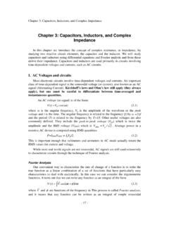
6 MFMcGraw-PHY 2426 Chap31-AC Circuits -Revised: 6/24/201235LC and RLC Circuits Without a GeneratorMFMcGraw-PHY 2426 Chap31-AC Circuits -Revised: 6/24/201236LC circuit - No GeneratorTo start this circuit some energy must be placed in it since there is no battery to drive the circuit . We will do that by placing a charge on the capacitorSince there is no resistor in the circuit and the resistance of the coil is assumed to be zero there will not be any 2426 Chap31-AC Circuits -Revised: 6/24/201237LC circuit - No GeneratorApply Kirchhoff s rule2222 RdIQL+= 0dtCdQSince I =dtd QQL+= 0dtCd Q1= -QdtLC1 =LCThis is the harmonic oscillator equationMFMcGraw-PHY 2426 Chap31-AC Circuits -Revised: 6/24/201238LC circuit - No Generator()pppQ(t) = Q cos tdQI(t) == - Q sin tdt I(t) = - Q cos t +2 The circuit will oscillate at the frequency R.
7 Energy will flow back and forth from the capacitor (electric energy) to the inductor (magnetic energy).MFMcGraw-PHY 2426 Chap31-AC Circuits -Revised: 6/24/201239 RLC circuit - No GeneratorLike the LC circuit some energy must initially be placed in this circuit since there is no battery to drive the circuit . Again we will do this by placing a charge on the capacitorSince there is a resistor in the circuit now there will be losses as the energy passes through the 2426 Chap31-AC Circuits -Revised: 6/24/201240 RLC circuit - No GeneratorApply Kirchhoff s rule22dIQdQL+ IR += 0 ; I =dtCdtd QdQ1L+ R+Q = 0dtdtC ma termDamping term - frictionRestoring force kx The damping term causes a damping of the natural oscillations of the 2426 Chap31-AC Circuits -Revised: 6/24/201241 RLC circuit - No GeneratorMFMcGraw-PHY 2426 Chap31-AC Circuits -Revised: 6/24/201242 RLC circuit - No Generator 2222222dIQL+ RI += 0dtCdIQILI+ I R += 0dtCd 1d 1 QLI+ I R += 0dt 2dt 2 Cd 11 QLI += -I Rdt 22 CThe rate of change of the stored energy= -Power dissipated in the resistorMultiply by IMFMcGraw-PHY 2426 Chap31-AC Circuits -Revised.
8 6/24/201243 Series RLC circuit with GeneratorWe have already examined the components in this circuit to understand the phase relations of the voltage and Current of each componentNow we will examine the power relationshipsMFMcGraw-PHY 2426 Chap31-AC Circuits -Revised: 6/24/201244 Series RLC circuit with Generatorpeakp(t) =sin t =sin t dI(t)Q(t)RI(t) + L+= (t)dtC Apply Kirchhoff s Loop rule to the circuit to0dQ= I Q(t) = Q +I(t')dt'dt t00dI(t)1RI(t) + L+I(t')dt' = (t); with Q = 0dtC MFMcGraw-PHY 2426 Chap31-AC Circuits -Revised: 6/24/201245 Series RLC circuit with Generator pttppp00 Steady state I(t) = I sin tIdI(t) = I cos t; I(t')dt' = I sin t'dt' = - cos t dt t0dI(t)1RI(t) + L+I(t')dt' = (t)dtC pppp1RI sin t + LI cos t -I cos t =sin t C MFMcGraw-PHY 2426 Chap31-AC Circuits -Revised: 6/24/201246 Series RLC circuit with Generator()() pppp1RI sin t + LI sin t ++I sin t -=sin t22 C Change all cos to sin by shifting the angleThe inductive voltage is 90o ahead of the currentThe capacitive voltage is 90o behind of the currentpppp1RI sin t + LI cos t -I cos t =sin t C MFMcGraw-PHY 2426 Chap31-AC Circuits -Revised: 6/24/201247 Impedance in a Series RLC circuit ()() pppp1RI sin t + LI sin t ++I sin t -=sin t22 C pppL pCpLCRLC RI LI I C X IX IX = LX = 1 CThe coefficients are voltagesThe R and XL and XC values are called impedances.
9 That is a generlized term for resistance since they all have units of is the inductive is the capacitive 2426 Chap31-AC Circuits -Revised: 6/24/201248 Power in a Series RLC CircuitNow we go back to the original equation and multiply bypI(t) = I sin tand integrate over one cycle: 0 => T 2 TTTTp2222ppp pooooIRIsin tdt + LI sin tcos tdt - sin tcos t dt = Isin tdt C pppp1RI sin t + LI cos t -I cos t =sin t C TT200sin tdt = sin t cos tdt = 0 MFMcGraw-PHY 2426 Chap31-AC Circuits -Revised: 6/24/201249 Power in a Series RLC Circuit2pppRI = E I Power is only dissipated in the resistor. The inductor stores energy in its magnetic field. The capacitor stores its energy in its electric in resistorPower out of batteryMFMcGraw-PHY 2426 Chap31-AC Circuits -Revised: 6/24/201250 Series RLC circuit with Generator t00dI(t)1RI(t) + L+I(t')dt' = (t); with Q = 0dtC We have used this equation to demonstrate the behavior of the three types of components: R, L and C, but-We still haven t solved the equationBefore we actually solve it we need to introduce complex variables that will be used in the 2426 Chap31-AC Circuits -Revised: 6/24/201251 The RC CircuitMFMcGraw-PHY 2426 Chap31-AC Circuits -Revised: 6/24/201252 The RC circuit - Low Freqpppp1RI sin t + LI cos t -I cos t =sin t C ppp1RI sin t -I cos t =sin t C Low Let L => 0 ppp1-I =(0) CI = 0 Open circuit For t0; cos t1.
10 Sin t0 MFMcGraw-PHY 2426 Chap31-AC Circuits -Revised: 6/24/201253 The RC circuit - High Freqppp1RI sin t -I cos t =sin t C High ppppppp1I sin t -I cos t =sin t CRRI sin t =sin tRI =R At high frequency the cap acts as a short high frequency the cap acts as a short circuit . 1 For CRMFMcGraw-PHY 2426 Chap31-AC Circuits -Revised: 6/24/201254 The RL CircuitMFMcGraw-PHY 2426 Chap31-AC Circuits -Revised: 6/24/201255 The RL circuit - Low Freqpppp1RI sin t + LI cos t -I cos t =sin t C Low pppRI sin t + LI cos t =sin t ppppRI sin t =sin tRI = At low frequency L acts as a short low frequency L acts as a short C => 0 For L1 MFMcGraw-PHY 2426 Chap31-AC Circuits -Revised: 6/24/201256 The RL circuit - High Freq For L1 High At high frequency L acts as an open high frequency L acts as an open sin t + LI cos t =sin t ppTT2pp00pp LI cos t =sin t multiply by cos t a