Transcription of Chapter 4: Gravity-Powered Systems - Free-Energy Devices ...
1 A Practical Guide to Free-Energy Devices Author: Patrick J. Kelly Chapter 4: Gravity-Powered Systems Note: If you are not at all familiar with basic electronics, you might find it easier to follow parts of this Chapter if you read Chapter 12 first. Lawrence Tseung s COP= Pulsed- flywheel Generator. It is generally not realised that excess energy can be obtained from pulsing a flywheel or other gravitational device. This fact has recently been stressed by Lawrence Tseung who refers to the extra energy obtained in this way as being Lead-out energy.
2 This gravitational feature has been part of university Engineering courses for decades, where it has been taught that the loading stress on a bridge caused by a load rolling across the bridge is far less than the stress caused if that same load were suddenly dropped on to the bridge. This impulse technology has been known for some time and it is demonstrated driving a canoe in the video at but Lawrence points out the potential for using it as a method for gaining excess energy for practical use. In October 2009, Lawrence and his band of helpers ran public demonstrations of an early prototype electrical pulsing system which produces excess output energy of COP = , that is, with times more output energy than the user has to put into it to make it work: 4 - 1 Video: Lawrence is busy developing this device further as he intends to construct one with a output energy excess of several kilowatts.
3 Behind this device is Lawrence's "Lead-out" theory and for this he suggests a simple arrangement to demonstrate the principle. He presents the case of a rotor which has two substantial weights contained in two cylinders attached to the rotor: As the disc rotates, the ball falls down the length of the tube. At one end, the tube has a rigid cap which causes a significant impact when the ball hits it. The other end of the tube is padded and that cushions the impact which causes a net imbalance in the impacts and that maintains the rotation. There is a prototype implementation on YouTube but the implementation is not adequate and the disc stops rotating after five minutes.
4 The YouTube video slot is located at: and there are two significant problems with that particular build. Firstly, the tube rotation is too slow to be effective and instead of the weight falling under gravity and accelerating to a good speed before the impact, the weight just rolls gently down a minor slope and does not make a major impact. Secondly, the weights are far too small for the size of the wheel and there are only two weights providing impacts very widely spaced apart as the wheel rotates only slowly. One man made a ten-foot version and it rotated steadily for ten months after which time his wife insisted that it be taken apart as it was too noisy.
5 I would suggest some modifications to the wheel as Lawrence is far too busy with developing his COP>1 pulse implementation. Firstly, the movement of each weight should be delayed until the tube is much nearer the vertical. This can be achieved by curving part of the tube like this: This way, the ball does not start rolling until the main part of the tube is near vertical. This allows a much greater acceleration and impact. The weighted ball should be much larger, say 2" (50 mm) in diameter and made of lead, in order to generate a significant thrust. Also, the cushioned ends of the tubes should be aligned with the pivot of the wheel so that any residual impact does not generate a turning force in the wrong direction.
6 There is a negative turning effect due to the lever arm of the bottom weight. This turning force is only there for a small arc of rotation as the weight will roll inwards as soon as the tube section rises above the horizontal and as the tube then transitions into a circular curve, the movement inwards is gentle. It probably would be better if the tubes were angled slightly more in the clockwise direction, rather than exactly as shown in the diagram. Secondly, there should be eight tubes on the disc, four on each side and one side staggered by 45 degrees so that there is a driving impact every 45 degrees instead of the 180 degrees of the version shown in the YouTube video.
7 With that arrangement of four times as many impacts, each substantially greater, and no significant reverse impacts, the wheel has a much better chance of successful rotation without needing to be particularly 4 - 2 large. The wheel itself should not be light as it acts as a flywheel and a pulsed flywheel has already been shown to produce excess power. The wheel bearings should be ball races and not the closed variety because those ones are packed with grease and have a serious resistance to rotation. Instead, the open-sided variety of ball bearing should be used as they rotate very freely.
8 Using straight tubes for illustration, each tube could be like this: Here, a wood disc is fitted to each end of a piece of plastic tube and held securely in place with screws or bolts which pass through small holes drilled in the plastic pipe and screw into the wooden disc. A piece of thick sponge is glued to the disc at one end and the heavy weight inside the tube is not a tight fit so that it can move very freely inside the tube. Four of these tubes are fitted to each side of each disc used in the device as shown here: The four tubes attached to the back of the disc are 45 degrees away from the tubes mounted on the front of the disc. Each tube is attached securely in place with straps which pass through the disc and are secured on the far side.
9 The tubes can also be glued in place to further strengthen the attachment. These eight tubes give an unbalanced impact for every 45 degrees of rotation. If two of these discs are attached to a common rotor shaft, then the second disc can be positioned degrees around from the first one. That arrangement gives an unbalanced impact for every degrees of rotation. If three discs were placed on a common rotor shaft and evenly positioned, then there would be an unbalanced impact every 15 degrees of rotation, which is 24 impacts per rotation. A two-disc arrangement might look like this: 4 - 3 If the rotor spins well, then it would be worth while attaching a series of magnets to the discs, being careful to keep each disc perfectly balanced.
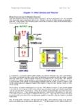
10 One or more air-core coils can then be used to determine if current can be drawn from the device without stopping the rotation. The coils should not have a magnetic core as that would cause a major drag on the rotation whether current was being drawn or not. Chas Campbell s flywheel system . Recently, Mr. Chas Campbell of Australia demonstrated electrical power gain with a flywheel system which he developed: 4 - 4 But what this diagram does not show, is that a couple of the drive belts are left with excessive slack. This causes a rapid series of jerks in the drive between the mains motor and the flywheel .