Transcription of Chapter 4 Planar Kinematics - MIT OpenCourseWare
1 Introduction to Robotics, H. Harry Asada 1 Chapter 4 Planar Kinematics Kinematics is Geometry of Motion. It is one of the most fundamental disciplines in robotics, providing tools for describing the structure and behavior of robot mechanisms. In this Chapter , we will discuss how the motion of a robot mechanism is described, how it responds to actuator movements, and how the individual actuators should be coordinated to obtain desired motion at the robot end-effecter. These are questions central to the design and control of robot mechanisms. To begin with, we will restrict ourselves to a class of robot mechanisms that work within a plane, Planar Kinematics .
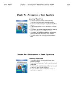
2 Planar Kinematics is much more tractable mathematically, compared to general three-dimensional Kinematics . Nonetheless, most of the robot mechanisms of practical importance can be treated as Planar mechanisms, or can be reduced to Planar problems. General three-dimensional Kinematics , on the other hand, needs special mathematical tools, which will be discussed in later chapters. Planar Kinematics of Serial Link Mechanisms Example Consider the three degree-of-freedom Planar robot arm shown in Figure The arm consists of one fixed link and three movable links that move within the plane. All the links are connected by revolute joints whose joint axes are all perpendicular to the plane of the links.
3 There is no closed-loop kinematic chain; hence, it is a serial link mechanism. x End Effecter Joint 1 Link 3 Link 2 Link 1 Joint 3 Joint 2A O 2A1Ay 1 Link 0 3A e 3 2 eeyx B E Figure Three dof Planar robot with three revolute joints To describe this robot arm, a few geometric parameters are needed. First, the length of each link is defined to be the distance between adjacent joint axes. Let points O, A, and B be the locations of the three joint axes, respectively, and point E be a point fixed to the end-effecter. Then the link lengths are EBBAAO===321,,AAA. Let us assume that Actuator 1 driving Department of Mechanical Engineering Massachusetts Institute of Technology Introduction to Robotics, H.
4 Harry Asada 2link 1 is fixed to the base link (link 0), generating angle 1 , while Actuator 2 driving link 2 is fixed to the tip of Link 1, creating angle 2 between the two links, and Actuator 3 driving Link 3 is fixed to the tip of Link 2, creating angle 3 , as shown in the figure. Since this robot arm performs tasks by moving its end-effecter at point E, we are concerned with the location of the end-effecter. To describe its location, we use a coordinate system, O-xy, fixed to the base link with the origin at the first joint, and describe the end-effecter position with coordinates eand e. We can relate the end-effecter coordinates to the joint angles determined by the three actuators by using the link lengths and joint angles defined above: xy )cos()cos(cos321321211 +++++=AAAex ( ) )sin()sin(sin321321211 +++++=AAAey ( ) This three dof robot arm can locate its end-effecter at a desired orientation as well as at a desired position.
5 The orientation of the end-effecter can be described as the angle the centerline of the end-effecter measured from the positive x coordinate axis. This end-effecter orientation e is related to the actuator displacements as 321 ++=e ( ) The above three equations describe the position and orientation of the robot end-effecter viewed from the fixed coordinate system in relation to the actuator displacements. In general, a set of algebraic equations relating the position and orientation of a robot end-effecter, or any significant part of the robot, to actuator or active joint displacements, is called Kinematic Equations, or more specifically, Forward Kinematic Equations in the robotics literature.
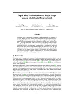
6 Exercise Shown below in Figure is a Planar robot arm with two revolute joints and one prismatic joint. Using the geometric parameters and joint displacements, obtain the kinematic equations relating the end-effecter position and orientation to the joint displacements. End Effecter Joint 1 Link 3 Link 2 Link 1 Joint 3 Joint 2y3A 1 e 3 x eeyx d E B O A Link 0 Figure Three dof robot with two revolute joints and one prismatic joint Department of Mechanical Engineering Massachusetts Institute of Technology Introduction to Robotics, H. Harry Asada 3 Now that the above Example and Exercise problems have illustrated kinematic equations, let us obtain a formal expression for kinematic equations.
7 As mentioned in the previous Chapter , two types of joints, prismatic and revolute joints, constitute robot mechanisms in most cases. The displacement of the i-th joint is described by distance di if it is a prismatic joint, and by angle i for a revolute joint. For formal expression, let us use a generic notation: qi. Namely, joint displacement qi represents either distance di or angle i depending on the type of joint. i{ iidq = ( ) Prismatic joint Revolute joint We collectively represent all the joint displacements involved in a robot mechanism with a column vector: , where n is the number of joints. Kinematic equations relate these joint displacements to the position and orientation of the end-effecter.}
8 Let us collectively denote the end-effecter position and orientation by vector p. For Planar mechanisms, the end-effecter location is described by three variables: [Tnqqqq"21=] =eeeyxp ( ) Using these notations, we represent kinematic equations as a vector function relating p to q: 113,),(nxxqpqfp = ( ) For a serial link mechanism, all the joints are usually active joints driven by individual actuators. Except for some special cases, these actuators uniquely determine the end-effecter position and orientation as well as the configuration of the entire robot mechanism. If there is a link whose location is not fully determined by the actuator displacements, such a robot mechanism is said to be under-actuated.
9 Unless a robot mechanism is under-actuated, the collection of the joint displacements, the vector q, uniquely determines the entire robot configuration. For a serial link mechanism, these joints are independent, having no geometric constraint other than their stroke limits. Therefore, these joint displacements are generalized coordinates that locate the robot mechanism uniquely and completely. Formally, the number of generalized coordinates is called degrees of freedom. Vector q is called joint coordinates, when they form a complete and independent set of generalized coordinates. Inverse Kinematics of Planar Mechanisms The vector kinematic equation derived in the previous section provides the functional relationship between the joint displacements and the resultant end-effecter position and orientation.
10 By substituting values of joint displacements into the right-hand side of the kinematic equation, one can immediately find the corresponding end-effecter position and orientation. The problem of finding the end-effecter position and orientation for a given set of joint displacements is referred to as the direct Kinematics problem. This is simply to evaluate the right-hand side of the kinematic equation for known joint displacements. In this section, we discuss the problem of moving the end-effecter of a manipulator arm to a specified position and orientation. We need to find the joint displacements that lead the end-effecter to the specified position and orientation.