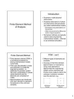
Transcription of Structural Axial, Shear P and Bending Moments V M
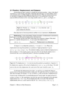
1 Recall from mechanics of mater- Structural Axial, Shear ials that the internal forces P. (generic axial), V ( Shear ) and M. and Bending Moments (moment) represent resultants of the stress distribution acting on the cross section of the beam. Internal Axial Force (P) equal in magnitude but opposite in direction to the algebraic sum (resultant) of the components in the direction parallel to the axis of the beam of all external loads and support reactions acting on either side of the section being considered. Positive Internal Forces Acting on a Portal Frame T Tension 1. C Compression 2. Internal Shear Force (V) equal in magnitude but opposite in direction to the algebraic sum (resultant) of the components in the direction perpendicular to the axis of the beam of all external loads and support reactions acting on either side of the section being considered. Internal Bending Moment (M) . equal in magnitude but opposite in direction to the algebraic sum of the Moments about (the centroid of the cross section of the beam) the Beam Sign Convention for section of all external loads and Shear and Moment support reactions acting on either 3.
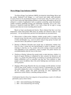
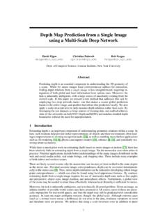
2 Side of the section being 4. considered. See also pages 17 - 34 in the supplemental notes. 1. Positive Sign Conventions: Shear and Bending moment diagrams depict the variation of Tension axial force on the section these quantities along the length Shears that produces clockwise of the member. Moments Proceeding from one end of the Bending Moments that produce member to the other, sections are compression in the top fibers and passed. After each successive tension in the bottom fibers of the change in loading along the beam length of the member, a FBD. (Free Body Diagram) is drawn to determine the equations express- ing the Shear and Bending mo- ment in terms of the distance from a convenient origin. Plotting these equations produces 5 the Shear and Bending moment 6. diagrams. Zero Shear . Maximum Positive Bending Moment V and M are in the opposite directions of the positive Shear and Bending Moment beam sign convention Diagrams 7 8.
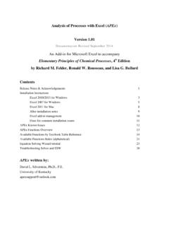
3 2. Principle of Superposition Example Problem Shear and Moment Diagrams Calculate and draw the Shear force and Bending moment equations for the given structure. 9 10. Sketching the Deflected Following our positive beam Shape of a Beam or Frame sign convention, a positive Bending moment bends a beam Qualitative Deflected Shape concave upward (or towards the (elastic curve) a rough (usually positive y direction), whereas a exaggerated) sketch of the neutral negative Bending moment surface of the structure in the bends a beam concave deformed position under the action downward (or towards the of a given loading condition. negative y direction). Such sketches provide valuable insights into the behavior of struc- tures. 11 12. 3. An accurate sketch must satisfy the following rules: The curvature must be consis- tent with the moment curve. The deflected shape must satisfy the boundary constraints.
4 The original angle at a rigid joint must be preserved. The length of the deformed member is the same as the original length of the unloaded member. 13 14. The horizontal projection of a beam or the vertical projection of a column is equal to the original length of the member. Axial deformations, which are trivial compared to Bending deformations, are neglected. Point of Inflection = zero moment location for mechanically loaded structures 15 16. 4. BC = zero member Bending B'C' straight line (linear). since MBC = 0. 17 18. Ignoring zero displacement at C. Enforcing zero displacement at Bending displacements C without support conditions 19 20. 5. BB' = CC'. = 'A from Fig. (a) Note discontinuity in rotation at C internal hinge location DD = DD' + A'A. from Fig. (a). Enforcing support conditions NOTE: Members AB' and C'D . displacements are linear since the Bending moment in these members is zero 21 22.
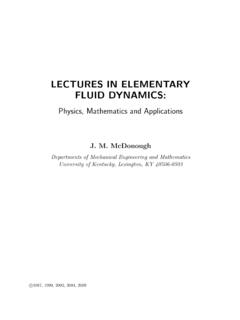
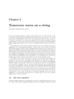
5 Axial Force, Shear Force and Bending Moment Diagrams for Plane Frames Previous definitions developed q for Shear forces and Bending P. Moments are valid for both beam B C. and frame structures. However, application of these definitions, developed for a horizontal beam, to a frame structure will require A D. some adjustments. Consider the portal frame shown Figure on the next two slides. (a) Loaded Portal Frame 23 24. 6. BC. M BC. B MC The positive sign convention consistent with beam theory is TBBC TCBC shown in (b). As seen from VBBC VCBC (b), the positive sign convention is (a) tension axial TBAB TCCD force, (b) Shear forces that produce clockwise Moments and M CD VCCD. VBAB C (c) Bending Moments that result in tension stresses in the interior M AB. B frame fibers. (b) The sign convention of (b) can be seen to be equivalent to the beam sign convention rotating AB CD columns AB and CD to line up VA VD.
6 M AB. A M CD. D with beam BC. AB CD. TA TD 25 26. NOTE: For multi-bay frames, Example Frame Problem 1. the usual practice is to define tension axial forces and shears that produce clockwise Moments as positive for each member. However, the inside fiber for Bending is not easily defined. Consequently, engineers choose to draw the Bending Moments on either the tension (common amongst Structural engineers) or compression side of the members. They are not labeled as either positive or negative. Calculate and draw the axial Alternatively, a vector sign force, Shear force and Bending convention can be used usual moment equations for the given for computer codes. 27. frame structure. 28. 7. Example Frame Problem 2 Two-Dimensional Force Transformations Py Px FT (a). r y x Pt Pn . Calculate and draw the axial FT (b). force, Shear force and Bending moment equations for the given frame structure. 29 FT = Force Transformation 30.
7 Suppose you are given the Pn Py . forces in FT (a) and you wish to transform these forces into Px . Pn Px sin Py cos . Pn (normal) and Pt (tangential). as shown in FT (b). This force transformation may be neces- sary so that you can calculate Pt Px cos Py sin . Pt the member axial and Shear Py forces.. These force transformations Px are summarized on the next x y slide. cos ; sin ;. r r y tan . 31. x 32. 8. Example Frame with Degree of Frame Inclined Member Indeterminacy Rigid Frame composed of straight members connected either by rigid (moment resisting). connections or by hinged connections to form stable configurations. Rigid Joint prevents relative translations and rotations between connected members. Calculate and draw the axial force, Shear force and Bending moment equations. 33 34. Statically Determinate the Summary Bending Moments , shears, 3m + R < 3j + C. and axial forces in all its statically unstable frame members, as well as the external reactions, can be 3m + R = 3j + C.
8 Determined by using the statically determinate equations of equilibrium and frame, if stable condition, otherwise the 3m + R > 3j + C. frame is either unstable or statically indeterminate. statically indeterminate frame, if stable I = (3m + R) - (3j + C). = degree of static indeterminacy 35. Redundants excess 36. members and reactions 9. Alternative Approach This alternative approach pro- vides the most convenient means An alternative approach for for determining the degree of determining the degree of static static indeterminacy of multistory indeterminacy of a frame is to building frames: cut enough members of the frame by passing imaginary I = 3(Ng Nf) Nh 2Nr C. sections and/or to remove Ng Number of Girders in the enough supports to render the structure statically determinate. structure The total number of internal and Nf Number of Free joints in the external restraints thus removed structure equals the degree of static Nh Number of Hinged supports indeterminacy.
9 Nr Number of Roller supports 37. C Number of equations of 38. Condition in the structure Equations of Condition at a Joint Detail w/ Three or More Members m = 5, R = 8. j = 6, C = 0. I=5. m = 4, R = 3. j = 4, C = 0. I=3. m = 6, R = 4. j = 6, C = 0. Cj = Nbj 1. I=4. Nbj = Number of Beam (moment resisting) members at joint j 39 I = (3m + R) (3j + C) 40. 10. m = 10, R = 9. j = 9, C = 5. Ng = 4, Nf = 0. Nh = Nr = 0. I=7. Ng = 4, Nf = 0 Ng = 35, Nf = 0. Nh = Nr = 0 Nh = Nr = 0. C=0 C=0. I = 12 I = 105. I = 3(Ng Nf) Nh 2Nr - C 41 42. 11.