Transcription of Chapter 5 Capacitance and Dielectrics
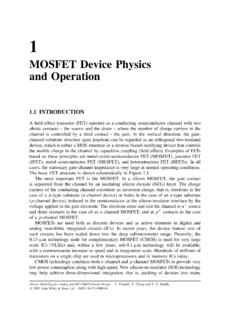
1 Chapter 5 Capacitance and Dielectrics Calculation of Example : Parallel-Plate Interactive Simulation : Parallel-Plate Example : Cylindrical Example : Spherical capacitors in Electric Parallel Series Example : Equivalent Storing Energy in a Energy density of the Electric Interactive Simulation : Charge Placed between Capacitor Example : Electric Energy density of Dry Example : Energy Stored in a Spherical Dielectrics without Dielectrics with Gauss s Law for Example : Capacitance with Creating Electric Animation : Creating an Electric Animation : Creating and Destroying Electric Appendix: Electric Fields Hold Atoms Ionic and van der Waals Interactive Simulation : Collection of Charges in Two Interactive Simulation : Collection of Charges in Three Interactive Simulation : Collection of Dipoles in Two Interactive Simulation : Charged Particle Interactive Simulation : Lattice Interactive Simulation : 2D Electrostatic Suspension Interactive Simulation : 3D Electrostatic Suspension Problem-Solving Strategy: Calculating Solved Equivalent Capacitor Filled with Two Different Capacitor with Capacitor Connected to a Conceptual Additional capacitors in Series and in capacitors and Gauss s Law in the Presence of a Gauss s Law and A Capacitor with a Force on the Plates of a Energy density in a Capacitor with a 5-2 Capacitance and Dielectrics Introduction A capacitor is a device which stores electric charge.
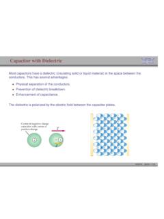
2 capacitors vary in shape and size, but the basic configuration is two conductors carrying equal but opposite charges (Figure ). capacitors have many important applications in electronics. Some examples include storing electric potential energy, delaying voltage changes when coupled with resistors, filtering out unwanted frequency signals, forming resonant circuits and making frequency-dependent and independent voltage dividers when combined with resistors. Some of these applications will be discussed in latter chapters. Figure Basic configuration of a capacitor. In the uncharged state, the charge on either one of the conductors in the capacitor is zero. During the charging process, a charge Q is moved from one conductor to the other one, giving one conductor a charge Q+, and the other one a charge . A potential difference is created, with the positively charged conductor at a higher potential than the negatively charged conductor.
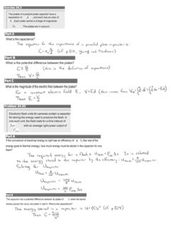
3 Note that whether charged or uncharged, the net charge on the capacitor as a whole is zero. Q V The simplest example of a capacitor consists of two conducting plates of area, which are parallel to each other, and separated by a distance d, as shown in Figure A Figure A parallel-plate capacitor Experiments show that the amount of charge Q stored in a capacitor is linearly proportional to, the electric potential difference between the plates. Thus, we may write V |QCV|= ( ) 5-3 where C is a positive proportionality constant called Capacitance . Physically, Capacitance is a measure of the capacity of storing electric charge for a given potential difference . The SI unit of Capacitance is the farad (: V F) 1 F1 farad 1 coulomb volt = 1 CV== A typical Capacitance is in the picofarad () to millifarad range, ().
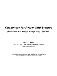
4 121 pF10F =361 mF10F=1000F; 1F10F == Figure (a) shows the symbol which is used to represent capacitors in circuits. For a polarized fixed capacitor which has a definite polarity, Figure (b) is sometimes used. (a) (b) Figure Capacitor symbols. Calculation of Capacitance Let s see how Capacitance can be computed in systems with simple geometry. Example : Parallel-Plate Capacitor Consider two metallic plates of equal area A separated by a distance d, as shown in Figure below. The top plate carries a charge +Q while the bottom plate carries a charge Q. The charging of the plates can be accomplished by means of a battery which produces a potential difference. Find the Capacitance of the system. Figure The electric field between the plates of a parallel-plate capacitor Solution: To find the Capacitance C, we first need to know the electric field between the plates.
5 A real capacitor is finite in size. Thus, the electric field lines at the edge of the plates are not straight lines, and the field is not contained entirely between the plates. This is known as 5-4edge effects, and the non-uniform fields near the edge are called the fringing fields. In Figure the field lines are drawn by taking into consideration edge effects. However, in what follows, we shall ignore such effects and assume an idealized situation, where field lines between the plates are straight lines. In the limit where the plates are infinitely large, the system has planar symmetry and we can calculate the electric field everywhere using Gauss s law given in Eq. ( ): enc0 Sqd = EAJGJGw By choosing a Gaussian pillbox with cap area A to enclose the charge on the positive plate (see Figure ), the electric field in the region between the plates is enc00 qA'EA'E0 == = ( ) The same result has also been obtained in Section using superposition principle.
6 Figure Gaussian surface for calculating the electric field between the plates. The potential difference between the plates is VVVdEd ++ = = = EsGG ( ) where we have taken the path of integration to be a straight line from the positive plate to the negative plate following the field lines (Figure ). Since the electric field lines are always directed from higher potential to lower potential, < VV +. However, in computing the Capacitance C, the relevant quantity is the magnitude of the potential difference: |V|Ed = ( ) and its sign is immaterial. From the definition of Capacitance , we have 5-5 0parallel plateAQC|V|d == () ( ) Note that C depends only on the geometric factors A and d.
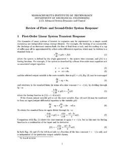
7 The Capacitance C increases linearly with the area A since for a given potential difference V , a bigger plate can hold more charge. On the other hand, C is inversely proportional to d, the distance of separation because the smaller the value of d, the smaller the potential difference ||V for a fixed Q. Interactive Simulation : Parallel-Plate Capacitor This simulation shown in Figure illustrates the interaction of charged particles inside the two plates of a capacitor. Figure Charged particles interacting inside the two plates of a capacitor. Each plate contains twelve charges interacting via Coulomb force, where one plate contains positive charges and the other contains negative charges. Because of their mutual repulsion, the particles in each plate are compelled to maximize the distance between one another, and thus spread themselves evenly around the outer edge of their enclosure.
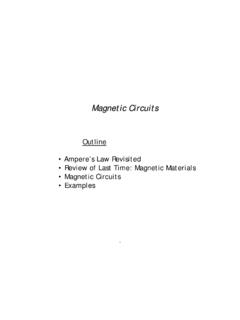
8 However, the particles in one plate are attracted to the particles in the other, so they attempt to minimize the distance between themselves and their oppositely charged correspondents. Thus, they distribute themselves along the surface of their bounding box closest to the other plate. Example : Cylindrical Capacitor Consider next a solid cylindrical conductor of radius a surrounded by a coaxial cylindrical shell of inner radius b, as shown in Figure The length of both cylinders is L and we take this length to be much larger than b a, the separation of the cylinders, so that edge effects can be neglected. The capacitor is charged so that the inner cylinder has charge +Q while the outer shell has a charge Q. What is the Capacitance ? 5-6(a) (b) Figure (a) A cylindrical capacitor. (b) End view of the capacitor. The electric field is non-vanishing only in the region a < r < b. Solution: To calculate the Capacitance , we first compute the electric field everywhere.
9 Due to the cylindrical symmetry of the system, we choose our Gaussian surface to be a coaxial cylinder with length and radius r where L<Aarb<<. Using Gauss s law, we have ()002 2 SdEAErEr === = EAAAJGJGw ( ) where /QL = is the charge per unit length. Notice that the electric field is non-vanishing only in the region ar. For rb<<a< , the enclosed charge is since any net charge in a conductor must reside on its surface. Similarly, for , the enclosed charge is enc0q=rb>enc0q = =AA since the Gaussian surface encloses equal but opposite charges from both conductors. The potential difference is given by 00ln22bbarabadrbVVVE drra = = = = ( ) where we have chosen the integration path to be along the direction of the electric field lines. As expected, the outer conductor with negative charge has a lower potential.
10 This gives 002||ln(/)/2ln(/)LQLCVbab === a ( ) Once again, we see that the Capacitance C depends only on the geometrical factors, L, a and b. 5-7 Example : Spherical Capacitor As a third example, let s consider a spherical capacitor which consists of two concentric spherical shells of radii a and b, as shown in Figure The inner shell has a charge +Q uniformly distributed over its surface, and the outer shell an equal but opposite charge Q. What is the Capacitance of this configuration? Figure (a) spherical capacitor with two concentric spherical shells of radii a and b. (b) Gaussian surface for calculating the electric field. Solution: The electric field is non-vanishing only in the region arb<<. Using Gauss s law, we obtain ()204rrSQdEAEr === EAJGJGw ( ) or 214roQEr = ( ) Therefore, the potential difference between the two conducting shells is: 200011444bbbaraaQdrQQbaVVVE drrab = = = = = ab ( ) which yields 04||QCVb == aba ( ) Again, the Capacitance C depends only on the physical dimensions, a and b.