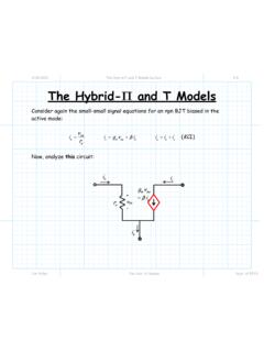
Transcription of Chapter 5 – Impedance Matching and Tuning - ITTC
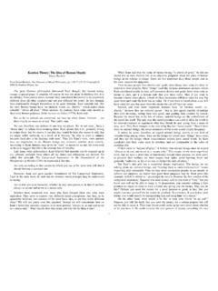
1 3/25/2009 section 5_1 Matching with Lumped elements 1/3 Jim Stiles The Univ. of Kansas Dept. of EECS Chapter 5 Impedance Matching and Tuning One of the most important and fundamental two-port networks that microwave engineers design is a lossless Matching network (otherwise known as an Impedance transformer). HO: Matching NETWORKS Q: In microwave circuits, a source and load are connected by a transmission line. Can we implement Matching networks in transmission line circuits? A: HO: Matching NETWORKS AND TRANSMISSION LINES Q: These Matching networks seem too good to be true can we really design and construct them to provide a perfect match? A: We can easily provide a near perfect match at precisely one frequency.
2 But, since lossless Matching and transmission lines are made of entirely reactive elements (not to mention the reactive components of source and load Impedance ), we find that changing the frequency will typically unmatch our circuit! 3/25/2009 section 5_1 Matching with Lumped elements 2/3 Jim Stiles The Univ. of Kansas Dept. of EECS Thus, a difficult challenge for any microwave design engineer is to design a wideband Matching network a Matching network that provides an adequate match over a wide range of frequencies. Generally speaking, Matching network design requires a trade-off between these for desirable attributes: 1. Bandwidth 2. Complexity 3. Implementation 4. Adjustability Matching with Lumped elements Reading Assignment: pp.
3 222-228 Now let s begin to examine how Matching networks are built! We begin with the simplest solution: An L-network, consisting of a single capacitor and a single inductor. Q: Just two elements ! That seems simple enough. Do we always use these L-networks when constructing lossless Matching networks? 3/25/2009 section 5_1 Matching with Lumped elements 3/3 Jim Stiles The Univ. of Kansas Dept. of EECS A: Nope. L-networks have two major drawbacks: 1. They are narrow-band. 2. Capacitors and inductors are difficult to make at microwave frequencies! Now, let s see how these L-networks actually work: HO: L-NETWORK ANALYSIS 3/12/2007 Matching Networks 1/9 Jim Stiles The Univ.
4 Of Kansas Dept. of EECS Matching Networks Consider again the problem where a passive load is attached to an active source: The load will absorb power power that is delivered to it by the source. {}{}222212121212 LLLgLggL gLLggLLggLPReVIVZRe VZZ ZZRe ZVZZRVZZ = = ++ =+=+ Recall that the power delivered to the load will be maximized (for a given gV and gZ) if the load Impedance is equal to the complex conjugate of the source Impedance (LgZZ =). Vg gZ LL LZRjX=+ 3/12/2007 Matching Networks 2/9 Jim Stiles The Univ.
5 Of Kansas Dept. of EECS We call this maximum power the available power avlP of the source it is, after all, the largest amount of power that the source can ever deliver! 22222121228maxLavlgggggggggPPRVZZRVRVR =+== * Note the available power of the source is dependent on source parameters only ( , gV and gR). This makes sense! Do you see why? * Thus, we can say that to take full advantage of all the available power of the source, we must to make the load Impedance the complex conjugate of the source Impedance . * Otherwise, the power delivered to the load will be less than power made available by the source! In other words : LavlPP 3/12/2007 Matching Networks 3/9 Jim Stiles The Univ.
6 Of Kansas Dept. of EECS A: NO! We can in fact modify our circuit such that all available source power is delivered to the load without in any way altering the Impedance value of that load! To accomplish this, we must insert a Matching network between the source and the load: The sole purpose of this Matching network is to transform the load Impedance into an input Impedance that is conjugate matched to the source! : LL LZRjX=+ Vg gggZRjX=+ Matching Network inV+ inI LV+ inI Q: But, you said that the load Impedance typically models the input Impedance of some useful device. We don t typically get to select or adjust this Impedance it is what it is. Must we then simply accept the fact that the delivered power will be less than the available power?
7 3/12/2007 Matching Networks 4/9 Jim Stiles The Univ. of Kansas Dept. of EECS *ininginVZZI== Because of this, all available source power is delivered to the input of the Matching network ( , delivered to inZ): inavlPP= LL LZRjX=+ Matching Network *ingZZ= Q: Wait just one second! The Matching network ensures that all available power is delivered to the input of the Matching network, but that does not mean (necessarily) that this power will be delivered to the load LZ. The power delivered to the load could still be much less than the available power!
8 3/12/2007 Matching Networks 5/9 Jim Stiles The Univ. of Kansas Dept. of EECS A: True! To ensure that the available power delivered to the input of the Matching network is entirely delivered to the load, we must construct our Matching network such that it cannot absorb any power the Matching network must be lossless! We must construct our Matching network entirely with reactive elements ! Examples of reactive elements include inductors, capacitors, transformers, as well as lengths of lossless transmission lines.
9 Thus, constructing a proper lossless Matching network will lead to the happy condition where: LinavlPP P== * Note that the design and construction of this lossless network will depend on both the value of source Impedance gZand load Impedance LZ. * However, the Matching network does not physically alter the values of either of these two quantities the source and load are left physically unchanged! Now, let s consider the Matching network from a different perspective. Instead of defining it in terms of its input Impedance when attached the load, let s describe it in terms of its output Impedance when attached to the source: 3/12/2007 Matching Networks 6/9 Jim Stiles The Univ.
10 Of Kansas Dept. of EECS This new source ( , the original source with the Matching network attached) can be expressed in terms of its Thevenin s equivalent circuit: This equivalent circuit can be determined by first evaluating (or measuring) the open-circuit output voltage ocoutV: outV+ Vg gggZRjX=+ Matching Network outI Vs outoutoutZRjX=+ ocoutV+ Vg gggZRjX=+ Matching Network 0outI= 3/12/2007 Matching Networks 7/9 Jim Stiles The Univ. of Kansas Dept. of EECS And likewise evaluating (or measuring) the short-circuit output current scoutI: From these two values ( and ocscoutoutVI) we can determine the Thevenin s equivalent source: ococoutsoutoutocoutVVVZI== Note that in general that sgVV and outgZZ the Matching network transforms both the values of both the Impedance and the voltage source.