Transcription of Chapter 6 Photoionization Detectors
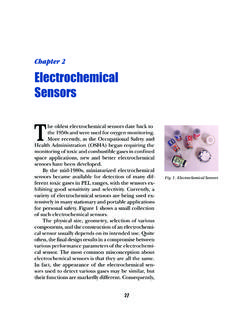
1 73 Chapter 6 Photoionization DetectorsChapter 6 PhotoionizationDetectorsThe Photoionization detector (PID) utilizes ultra-violet light to ionize gas molecules, and is com-monly employed in the detection of volatile or-ganic compounds (VOCs). This technique originallyfound use in bench top laboratory instruments, butits complexity limited its use elsewhere. The heart ofthe Photoionization detector is an ultraviolet source,which is essentially a lamp. Early versions of this lampused electrodes inside the lamp similar to those usedin the early days of the vacuum tube and were quitecostly to lamps used today do not contain electrodesand are both less costly and have a longer life expect-ancy. In the 1980s, with the advent of integrated cir-cuit (IC) technology, the electronics that were de-signed were better able to process the small signal fromPID sensors into useful and reliable , requirements for the monitoringof underground storage tanks to help preventground water contamination began to emerge,which required monitoring of events led to the design of small, portablePIDs (see Figure 1) that have proven to be both prac-tical and reliable, and which offer fast response andthe ability to detect low gas concentrations.
2 To thisFig. 1 A Pocket PID Monitor74 Hazardous Gas Monitorsday, PID sensors are the preferred choice for the de-tection of of OperationUltraviolet (UV) light is the radiation group thathas frequencies that are higher and are directly abovevisible light in the electromagnetic radiation wavelengths, being in the nanometer ( m = 10-9meters) region, are much shorter than IR wavelengths of infrared light used for gas analy-sis are in the micron region, 10- 6 shorter wavelengths have higher frequen-cies, and hence more energy, UV radiation has moreenergy than IR radiation. UV radiation energy levelsare commonly described in terms of electron volts, Wavelength is related to eV through Planck s Con-stant2 which is x 10-5 eV. [An electron volt x 10-6/wavelength ( m).]
3 The term eV is usedfor convenience, to give a simple numerical expres-sion of the radiant strength.]The PID Lamp. The heart of the detector is thePID lamp which has an exterior shape resembling amedical ampule and comes in different sizes and di-mensions, depending on the manufacturer. The lampis filled with a low-pressure inert gas. When this gas isenergized with energy in resonance with the naturalfrequency of the gas molecules, an ultraviolet spec-tral radiation is wavelength of the UV light emitted dependson the type of gas in the lamp. For instance, krypton,when excited, will emit m and m radia-tion, or the equivalent of 10 eV and eV. This lamp happens to be the most popular lamp cur-rently used in PID instruments. Various other gasesare also used.
4 Figure 2 on the following page showswavelengths emitted by argon, kr ypton, and different techniques are employed to powerthe PID lamp. A high voltage is required for the lamp1eV = energy gained when a particle ofone electronic charge is acceleratedthrough a potential of one s Constant is a fundamental con-stant in quantum physics. The radiantenergy only changes in quanta ordiscrete 6 Photoionization Detectorsto function. The source needs to remain stable overtime and also be efficient, so as not to consume toomuch power. A typical design would place electrodesinside the lamp. These types of lamps look similar tothe vacuum tubes used in the early days of radio andTV. There are electrical terminations on the tube, andthe gas discharge is confined to a small capillary.
5 Whilethe voltage used is in excess of 1000 volts, the currentis very low. Although this type of lamp is used in manylaboratories, it is quite expensive. As a result, a morepopular lamp in use today is the electrodeless Electrodeless Lamp. This lamp is only filledwith a low-pressure inert gas and there are no elec-trodes inside the lamp. The simplicity of this designallows the lamp to be miniaturized, making the de-sign of the portable instrumentation very the electrodeless lamp, the low-pressure inertgas is separated by the lamp wall from the outsideworld. Because there are no electrodes that providepower directly to the gas, the only way to excite theFig. 2 The wavelengths ( m) emitted by argon, krypton, and xenon. Gas Monitorsgas molecules is to use radiation energy that can pen-etrate the lamp are several different ways this can be accom-plished.
6 One method is to use electromagnetic radia-tion. A more popular technique, however, is to placea pair of electrodes on the exterior wall of the lamp. Ahigh-voltage, low-current charge is applied to the elec-trodes, and the energy applied is sufficient to excitethe low-pressure gas inside the lamp. The design issimilar to that of a fluorescent light used in a home oroffice, except on a much smaller Window Materials. At the wavelength ofradiation, meaning the wave frequency of UV light,most materials will absorb the radiation and preventthe transmission of such , special window materials are placed atthe discharge end of the lamp which allow spectralemissions to pass through. This window material is acrystal that allows good transmission of the targetedUV wavelength.
7 For instance, eV lamps commonlyuse krypton gas and magnesium fluoride windows,while eV lamps, which have more energy, use ar-gon gas and lithium fluoride windows. These windowsare soft glass and are very fragile. They are quite ex-pensive, and require special care and handling. Fig-ure 3 illustrates typical PID MoleculesSignal iElectrodeElectrode Platefor Lamp IlluminationLamp+V-InsulationWindowFig. 3 A Typical Photoionization Detector Configuration77 Chapter 6 Photoionization DetectorsA pair of electrode plates are placed in close prox-imity to the lamp window where the light is electrodes are biased with a stable DC voltagewhich will generate signals in case any small changesin the electrical field occur. As gas molecules moveinto the radiated field in the space between the elec-trodes, they are ionized and the free electrons arecollected at the electrodes resulting in a current flowwhose magnitude is directly proportional to the ionization Potentials.
8 Each gas has itsown unique ionization potential (IP). Gases with IP val-ues below the eV output of the lamp will be most portable instruments, the eV lamp ismost widely used because it detects most volatile or-ganic compounds, and the lamp is easy to clean. How-ever, other lamps are also available, including 10 eV, eV, eV, and eV lamps. Most manufactur-ers design instruments with a lamp chamber that al-lows easy interchange of lamps. The ionization po-tentials for many gases are included in Appendix II atthe end of this are examples of gases detectable usingdifferent detected by eV lamp such as benzene,aromatic compounds, Gases detected between eV and eV such asammonia, ethanol, Gases detected between eV and eV such asacetylene, formaldehyde, eV lamp will ionize gases with ionizationpotentials below eV and will not ionize gases withhigher ionization potentials.
9 On the other hand, ifone uses an eV lamp, gases with ionization po-tentials up to eV will be ionized. Interchanginglamps in an unknown air sample helps to separate itinto groups of Gas MonitorsCharacteristicsPID sensors offer fast response for detection ofmany volatile organic compounds. They will respondto all gases that have ionization potentials equal to orless than the eV output of their Factor. PIDs are typically calibratedwith isobutylene, a stable gas with a slightly pungentodor. This gas is easy to handle and can be stored athigh pressure, allowing calibration bottles to providemany calibrations. PID instruments typically detectgases at low concentrations, and most of these gasesare normally liquid solvents or other gases that arenot easy to calibrate.
10 Thus, it is much easier to cali-brate these instruments using isobutylene as the cali-bration gas. Readings for other gases are obtained bymultiplying the reading by a correction factor. For ex-ample, benzene has a correction factor of , whichmeans that a reading of 100 ppm isobutylene on thesensor indicates a concentration of 50 ppm ammonia, which has a response factor of 10, areading of 100 ppm on the sensor would indicate anammonia concentration of 1000 ppm. Instrumentmanufacturers typically supply a list of correction fac-tors with their important point to remember is that correc-tion factors are not absolute, and data can be slightlydifferent from manufacturer to manufacturer. In fact,these factors can even vary somewhat from lamp tolamp, and the results may vary depending on the qual-ity of the UV output of the lamp at the time of mea-surement.