Transcription of Chapter 9: Column Analysis and Design
1 Chapter 9: Column Analysis and Design Introduction columns are usually considered as vertical structural elements, but they can be positioned in any orientation ( diagonal and horizontal compression elements in a truss). columns are used as major elements in trusses, building frames, and sub-structure supports for bridges ( piers). columns support compressive loads from roofs, floors, or bridge decks. columns transmit the vertical forces to the foundations and into the subsoil. The work of a Column is simpler than the work of a beam. The loads applied to a Column are only axial loads. Loads on columns are typically applied at the ends of the member, producing axial compressive stresses. However, on occasion the loads acting on a Column can include axial forces, transverse forces, and bending moments ( beam- columns ). columns are defined by the length between support ends.
2 Short columns ( footing piers). Long columns ( bridge and freeway piers). Virtually every common construction material is used for Column construction. Steel, timber, concrete (reinforced and pre-stressed), and masonry (brick, block, and stone). The selection of a particular material may be made based on the following. Strength (material) properties ( steel vs. wood). Appearance (circular, square, or I-beam). Accommodate the connection of other members. Local production capabilities ( the shape of the cross section). columns are major structural components that significantly affect the building s overall performance and stability. columns are designed with larger safety factors than other structural components. Failure of a joist or beam may be localized and may not severely affect the building s integrity ( there is redundancy with girders and beams, but not with columns ).
3 Failure of a strategic Column may be catastrophic for a large area of the structure. Failure may be due to overstressed, loss of section (deterioration), accident/sabotage (terrorism). Safety factors for columns are used to account for the following. Material irregularities ( out of straightness). Support fixity at the Column ends. Construction inaccuracies ( out of plumbness). Workmanship. Unavoidable eccentric (off-axis) loading. Short and Long columns Modes of Failure Column slenderness and length greatly influence a Column s ability to carry load. Very short, stout columns fail by crushing due to material failure. - Failure occurs once the stress exceeds the elastic (yield point) limit of the material. Long, slender columns fail by buckling a function of the Column s dimensions and its modulus of elasticity. - Buckling is the sudden uncontrolled lateral displacement of a Column at which point no additional load can be supported.
4 - Failure occurs at a lower stress level than the Column s material strength due to buckling ( lateral instability). Short columns Short columns fail by crushing at very high stress levels that are above the elastic limit of the Column material. Compressive stress for short columns is based on the basic stress equation developed at the beginning of Chapter 5. If the load and Column size ( cross-sectional area) are known, the compressive stress may be computed as fa = Pactual/A Fa where fa = actual compressive stress (psi or ksi) A = cross-sectional area of the Column (in2) Pactual = actual load on the Column (pounds or kips) Fa = allowable compressive stress per code (psi or ksi) This stress equation can be rewritten into a Design form to determine the required short Column size when the load and allowable material strength are known.
5 Arequired = Pactual/Fa where Arequired = minimum cross-sectional area of the Column Long columns Euler Buckling Long columns fail by buckling at stress levels that are below the elastic limit of the Column material. Very short Column lengths require extremely large loads to cause the member to buckle. Large loads result in high stresses that cause crushing rather than buckling. Buckling in long, slender columns is due to the following. Eccentricities in loading. Irregularities in the Column material. Buckling can be avoided (theoretically) if the loads were applied absolutely axially, the Column material was totally homogeneous with no imperfections, and construction was true and plumb. A Swiss mathematician named Leonhard Euler (1707 1783) was the first to investigate the buckling behavior of slender columns within the elastic limit of the Column s material.
6 Euler s equation shows the relationship between the load that causes buckling of a (pinned end) Column and the material and stiffness properties of the Column . The critical buckling load can be determined by the following equation. Pcritical = 2 EImin/L2 where Pcritical = critical axial load that causes buckling in the Column (pounds or kips) E = modulus of elasticity of the Column material (psi or ksi) Imin = smallest moment of inertia of the Column cross-section (in2) (Most sections have Ix and Iy; angles have Ix, Iy and Iz.) L = Column length between pinned ends (inches) As the Column length increases, the critical load rapidly decreases (since it is proportional to L2), approaching zero as a limit. The critical load at buckling is referred to as Euler s critical buckling load. Euler s equation is valid only for long, slender columns that fail due to buckling.
7 Euler s equation contains no safety factors. Euler s equation results in compressive stresses developed in columns that are well below the elastic limit of the material. Slenderness Ratios The radius of gyration is a geometric property of a cross section that was first introduced in Chapter 6. I = Ar2 and r = (I/A) 1/2 where r = radius of gyration of the Column cross section (in) I = least (minimum) moment of inertia (in4) A = cross-sectional area of the Column (in2) The radius of gyration is geometric property that is used in the Analysis and Design of columns . Using the radius of gyration, the critical stress developed in a long Column at buckling can be expressed by the following equation. fcritical = Pcritical/A = 2 EImin/AL2 = 2E(Ar2)/AL2 = 2E/(L/r)2 The term L/r is known as the slenderness ratio. A higher slenderness ratio means a lower critical stress that will cause buckling.
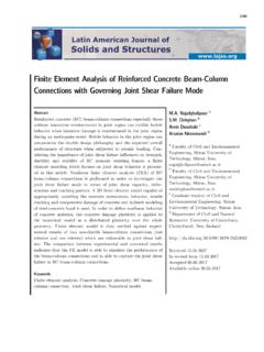
8 Conversely, a lower slenderness ratio results in a higher critical stress (but still within the elastic range of the material). Column sections with large r-values are more resistant to buckling. Compare the difference in rmin values and slenderness ratios for the three Column cross sections shown below. - All three cross sections have relatively equal cross-sectional areas but very different radii of gyration about the critical buckling axis. - All three columns are assumed to be 15 feet in length and pin-connected at both ends. Comparison of steel cross sections with equivalent areas The most efficient Column sections for axial loads are those with almost equal rx and ry values. Circular pipe sections and square tubes are the most effective shapes since the radii of gyration about both axes are the same (rx = ry). Circular pipe sections and square tubes are often used as columns for light to moderate loads.
9 Wide-flange shapes may be preferred despite the structural advantages of closed cross-sectional shapes (like tubes and pipes). The practical considerations of wide-flange shapes include the following. - Wide-flange sections support heavy loads. - Wide-flange sections accommodate beam connections. Special wide-flange sections are specifically manufactured to provide relatively symmetrical columns (rx/ry ratios approaching ) with large load-carrying capability. Most of these Column sections (generally W8, W10, W12, and W14) have depth and flange widths approximately equal ( a boxy configuration). End Support Conditions and Lateral Bracing Previously, each Column was assumed to have pinned ends in which the member ends were free to rotate (but not translate) in any direction at their ends. When the Column buckles, it will do so in one smooth curve.
10 The length of this curve is referred to as the effective length. In practice, a Column may not be pinned at the ends. The Column length free to buckle is greatly influenced by its end support conditions. The load-carrying capacity of a Column is affected by the end support conditions. - Restraining the ends of a Column with a fixed support increases the load-carrying capacity of a Column . - Allowing translation as well as rotation ( free end) at one end of a Column generally reduces its load-carrying capacity. Column Design formulas generally assume a condition in which both ends are pinned. When other conditions exist, the load-carrying capacity is increased or decreased and the allowable compressive stress is increased or decreased. A factor K is used as a multiplier for converting the actual Column length to an effective buckling length based on end conditions.