Transcription of Learning Earthquake Tip 20 Earthquake Design Construction
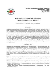
1 How do Beam- column joints in RC Buildings resist Earthquakes? Earthquake Tip 20 Learning Earthquake Design and ConstructionWhy Beam- column joints are Special In RC buildings, portions of columns that are common to beams at their intersections are called beam- column joints (Figure 1). Since their constituent materials have limited strengths, the joints have limited force carrying capacity. When forces larger than these are applied during earthquakes, joints are severely damaged. Repairing damaged joints is difficult, and so damage must be avoided. Thus, beam- column joints must be designed to resist Earthquake effects.
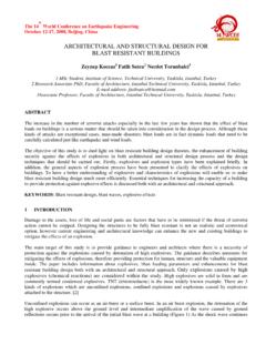
2 Earthquake Behaviour of Joints Under Earthquake shaking, the beams adjoining a joint are subjected to moments in the same (clockwise or counter-clockwise) direction (Figure 1). Under these moments, the top bars in the beam-column joint are pulled in one direction and the bottom ones in the opposite direction (Figure 2a). These forces are balanced by bond stress developed between concrete and steel in the joint region. If the column is not wide enough or if the strength of concrete in the joint is low, there is insufficient grip of concrete on the steel bars. In such circumstances, the bar slips inside the joint region, and beams loose their capacity to carry load.
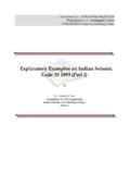
3 Further, under the action of the above pull-push forces at top and bottom ends, joints undergo geometric distortion; one diagonal length of the joint elongates and the other compresses (Figure 2b). If the column cross-sectional size is insufficient, the concrete in the joint develops diagonal cracks. Reinforcing the Beam-Column joint Diagonal cracking & crushing of concrete in joint region should be prevented to ensure good Earthquake performance of RC frame buildings. Using large column sizes is the most effective way of achieving this. In addition, closely spaced closed-loop steel ties are required around column bars (Figure 3) to hold together concrete in joint region and to resist shear forces.
4 Intermediate column bars also are effective in confining the joint concrete and resisting horizontal shear forces. Providing closed-loop ties in the joint requires some extra effort. Indian Standard IS:13920-1993 recommends continuing the transverse loops around the column bars through the joint region. In practice, this is achieved by preparing the cage of the reinforcement (both longitudinal bars and stirrups) of all beams at a floor level to be prepared on top of the beam formwork of that level and lowered into the cage (Figures 4a and 4b). However, this may not always be possible particularly when the beams are long and the entire reinforcement cage becomes heavy.
5 Anchoring Beam Bars The gripping of beam bars in the joint region is improved first by using columns of reasonably large cross-sectional size. As explained in Earthquake Tip 19, the Indian Standard IS:13920-1993 requires building columns in seismic zones III, IV and V to be at least 300mm wide in each direction of the cross-section when they support beams that are longer than 5m or when these columns are taller than 4m between floors (or beams). The American Concrete Institute recommends a column width of at least 20 times the diameter of largest longitudinal bar used in adjoining beam.
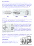
6 Figure 1: Beam- column joints are critical parts of a building they need to be designed. Beam-Column joint Overlap volumecommon to beamsand columns (a) (b) Figure 2: Pull-push forces on joints cause two problems these result in irreparable damage in joints under strong seismic shaking. Gripping of bar inside joint region CompressionTensionLoss of grip on beam bars in joint region: Large column width and good concrete help in holding the beam bars Distortion of joint : causes diagonal cracking and crushing of concrete Figure 3: Closed loop steel ties in beam- column joints such ties with 135 hooks resist the ill effects of distortion of joints.
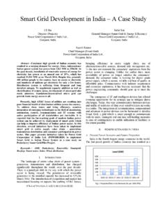
7 Closed ties BeamColumn10 times diameter of tie135 39 Intermediate Column Bars IITK-BMTPC Earthquake Tip 20 How do Beam- column joints in RC Buildings resist Earthquakes? page 2 In exterior joints where beams terminate at columns (Figure 5), longitudinal beam bars need to be anchored into the column to ensure proper gripping of bar in joint . The length of anchorage for a bar of grade Fe415 (characteristic tensile strength of 415 MPa) is about 50 times its diameter. This length is measured from the face of the column to the end of the bar anchored in the column. In columns of small widths and when beam bars are of large diameter (Figure 5a), a portion of beam top bar is embedded in the column that is cast up to the soffit of the beam, and a part of it overhangs.
8 It is difficult to hold such an overhanging beam top bar in position while casting the column up to the soffit of the beam. Moreover, the vertical distance beyond the 90 bend in beam bars is not very effective in providing anchorage. On the other hand, if column width is large, beam bars may not extend below soffit of the beam (Figure 5b). Thus, it is preferable to have columns with sufficient width. Such an approach is used in many codes [ , ACI318, 2005]. In interior joints, the beam bars (both top and bottom) need to go through the joint without any cut in the joint region.
9 Also, these bars must be placed within the column bars and with no bends (Figure 6). Related - Earthquake Tip Tip17: How do Earthquakes Affect Reinforced Concrete Buildings? Tip18: How do Beams in RC Buildings Resist Earthquakes? Tip19: How do columns in RC Buildings Resist Earthquakes? Reading Material ACI 318, (2005), Building Code Requirements for Structural Concrete and Commentary, American Concrete Institute, USA IS 13920, (1993), Indian Standard Code of Practice for Ductile Detailing of Reinforced Concrete Structures Subjected to Seismic Forces, Bureau of Indian Standards, New Delhi SP 123, (1991), Design of Beam- column joints for Seismic Resistance, Special Publication, American Concrete Institute, USA This release is a property of IIT Kanpur and BMTPC New Delhi.
10 It may be reproduced without changing its contents and with due acknowledgement. Suggestions/comments may be sent to: Visit or , to see previous IITK-BMTPC Earthquake Tips. Authored by: Indian Institute of Technology Kanpur Kanpur, India Sponsored by: Building Materials and Technology Promotion Council, New Delhi, India Figure 6: Anchorage of beam bars in interior joints diagrams (a) and (b) show cross-sectional views in plan of joint region. (a) Poor Practice Beam bars bent in joint region overstress the core concrete adjoining the bends Beam bars are within column bars and also straight(b) Good PracticeFigure 5: Anchorage of beam bars in exterior joints diagrams show elevation of joint region.